Do you have a question about the Trane Sintesis RTAF and is the answer not in the manual?
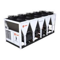
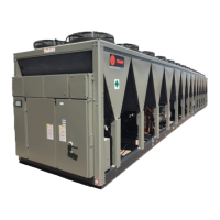
Details the Trane Sintesis Air-Cooled Chillers, Model RTAF.
Provides essential safety advisories for operating and servicing the unit.
Discusses scientific research on chemicals affecting the ozone layer.
Highlights Trane's commitment to responsible refrigerant handling.
Outlines requirements to preserve the factory warranty.
States Trane's ownership of the document and rights to revise.
Identifies trademarks referenced in the document.
Details information provided on unit and compressor nameplates.
Explains the composition and meaning of unit model numbers.
Breaks down the unit model number digits and their meanings.
Describes the components of the compressor model number.
Explains the structure of the compressor serial number.
Lists accessories and loose parts shipped with the unit.
Provides a table of general unit data, including capacities and specifications.
Guides on verifying the unit upon delivery and reporting damage.
Checklist for inspecting unit for damage before storage.
Provides precautions for extended unit storage.
Lists contractor responsibilities for unit installation.
Illustrates required clearances for unit operation and maintenance.
Refers to submittals for specific unit dimensions.
Presents shipping and operating weights for different unit sizes.
Details considerations for unit placement, including sound.
Specifies requirements for unit foundation and leveling.
Provides information on maintaining adequate space around the unit.
Offers safety warnings and procedures for lifting and moving the unit.
Explains methods for reducing sound and vibration transmission.
Details installing optional isolators and leveling the unit.
Provides guidance on chilled water piping installation.
Explains locating units near drains for maintenance.
Emphasizes the importance of proper water treatment for equipment.
Covers evaporator water connections and flushing procedures.
Lists components for proper water system operation and safety.
Details requirements for entering chilled water piping.
Details requirements for leaving chilled water piping.
Describes waterbox drain and vent connections.
Guides on installing and reading pressure gauges.
Instructions for installing water pressure relief valves.
Explains the operation and installation of the evaporator flow switch.
Presents evaporator water pressure drop curves.
Details methods to protect the chiller from ambient freeze damage.
Shows low evaporator temperature cutout for different glycol levels.
Provides general guidelines for electrical installations.
Details components that the installer must supply.
Instructions for power supply wiring, emphasizing copper conductors.
Notes that the unit has a control power transformer.
Explains the heater power supply for freeze protection.
Describes the operation of the chilled water pump control.
Explains the concept of programmable relays for events and states.
Details how to assign events/states to relays using Tracer TU.
Provides guidelines for low voltage wiring.
Describes the function and wiring of the emergency stop.
Explains the external auto/stop function and wiring.
Details the ice building option and its control.
Describes the ECWS option for setting chilled water setpoints.
Provides wiring details for EDLS and ECWS analog inputs.
Explains CWR function for adjusting chilled water setpoint.
Introduces the Trane TR200 AFD drive and its features.
Details the installation and jumper removal for the AFD drive.
Guides on programming AFD drives using the keypad interface.
Describes LonTalk, BACnet, and Modbus communication interfaces.
Describes the components of the refrigerant circuit.
Illustrates the typical refrigerant cycle using a pressure-enthalpy diagram.
Specifies refrigerants and oils to use and discusses responsible practices.
Details the rotary screw compressor and its lube oil system.
Describes the air-cooled microchannel condenser coils and fans.
Explains the tube-in-shell heat exchanger design of the evaporator.
Lists control and interface components used in the chillers.
Covers information pertaining to the UC800 controller hardware.
Illustrates UC800 controller ports, LEDs, and wiring terminals.
Details the four connections supporting communication interfaces.
Explains the function of rotary switches for setting addresses.
Describes the behavior of UC800 LEDs.
Information tailored for operators, service technicians, and owners.
Describes the TD7 display for accessing chiller information.
Explains the home screen's display of frequently needed chiller status.
Guides on viewing current operating status and submodes.
Instructions for viewing and resetting alarms.
Details how to view and create custom reports.
Steps for adding, removing, or re-ordering data in custom reports.
Guides on changing various equipment settings via the TD7 display.
Provides access to settings for chiller operation.
Provides access to settings for unit features.
Details the settings for chilled water reset functionality.
Instructions for changing display format and cleaning the screen.
Guides on changing date, time, units, and other display preferences.
Instructions for changing the display language.
Details how to change the display's date and time settings.
Procedure to disable the touchscreen for cleaning.
Explains the security feature to protect settings changes.
Steps to disable or enable the security feature.
Instructions for logging into the security system with a PIN.
Procedure to log out of the security system.
Information on the Tracer TU service tool for chiller servicing.
Provides critical notice regarding compressor and oil sump heaters.
Procedure for a short-term shutdown and restart.
Details the procedure for extended unit shutdown.
Step-by-step guide for seasonal unit start-up.
Procedures to restart the unit after a prolonged shutdown period.
Provides basic information on chiller operation for common events.
Diagram illustrating the five possible software states of the chiller.
Explains timeline indicators for operating modes and software states.
Shows the sequence of operation during a unit power up.
Diagram showing timing from power up to energizing the first compressor.
Diagram showing timing from stopped mode to energizing the first compressor.
Illustrates the typical start and run sequence for the lead compressor.
Illustrates the typical start and run sequence for the lag compressor.
Shows the normal transition from Running to shutdown due to water temp.
Depicts the transition from Running through a normal shutdown.
Shows the transition from Running through an immediate shutdown.
Illustrates the transition from normal cooling to ice making and back.
Shows the transition from Auto to Ice making to Ice Making Complete.
Provides maintenance procedures and recommended intervals.
Lists weekly maintenance tasks, including checks and observations.
Details monthly maintenance tasks, including recording system data.
Outlines annual maintenance procedures and inspections.
Emphasizes proper refrigerant and oil charge for unit operation.
Details the procedure for checking the oil sump level.
Explains the importance and procedure for cleaning condenser coils.
Provides instructions and warnings for cleaning condenser coils.
Defines diagnostic terminology, sources, targets, severity, and persistence.
Lists and explains diagnostics related to the AFD drive.
Details diagnostics related to the starter motor and its operation.
Covers diagnostics generated by the main processor.
Lists diagnostics related to communication loss between components.
Lists drawing numbers for electrical schematics and diagrams.
Form for installation verification and service request.
Log sheet for recording operational data.
Form for installation verification and service request.
| Refrigerant | R-134a |
|---|---|
| Compressor Type | Screw |
| Efficiency | High efficiency |
| Dimensions | Varies by model |
| Sound | Low Sound |
| Control System | Trane Tracer UC800 |
| Weight | Varies with model |