Installation Mechanical
RTAF-SVX001A-EN 19
Entering Chilled Water Piping
• Air vents to bleed the air from the system (to be placed
on the highest point)
• Water pressure gauges with shutoff valves
• Vibration eliminators
• Shutoff (isolation) valves
• Thermometers if desired (temperature readings
available on chiller controller display)
• Clean-out tees
• Pipe strainer
Leaving Chilled Water Piping
• Air vents to bleed the air from the system (to be placed
on the highest point)
• Water pressure gauges with shut off valves
• Vibration eliminators
• Shutoff (isolation) valves
• Thermometers (temperature readings available on the
chiller controller display)
• Clean-out tees
• Balancing valve
Waterbox Drains and Vents
RTAF chillers are equipped with two ½” drain connections:
one located on each waterbox. Waterboxes also include
vent connections to assist in bleeding air from the chilled
water loop.These vent connections should not be
assumed to be capable of venting attached chilled water
piping.
Note: If evaporator will be drained for winter storage, the
heaters must be disconnected to prevent
overheating.To drain properly, use pressurized air
to ensure all water is removed from the evaporator.
Pressure Gauges
Install field-supplied pressure components as shown in
Table 9, p. 19. Locate pressure gauges or taps in a straight
run of pipe; avoid placing them near elbows.
To read manifold pressure gauges, open one valve and
close the other (depending on the side of the desired
reading) to prevent errors resulting from differently
calibrated gauges installed at unmatched elevations.
Pressure Relief Valves
Install a water pressure relief valve in the evaporator inlet
piping between evaporator and the inlet shutoff valve.
Water vessels with close-coupled shutoff valves have high
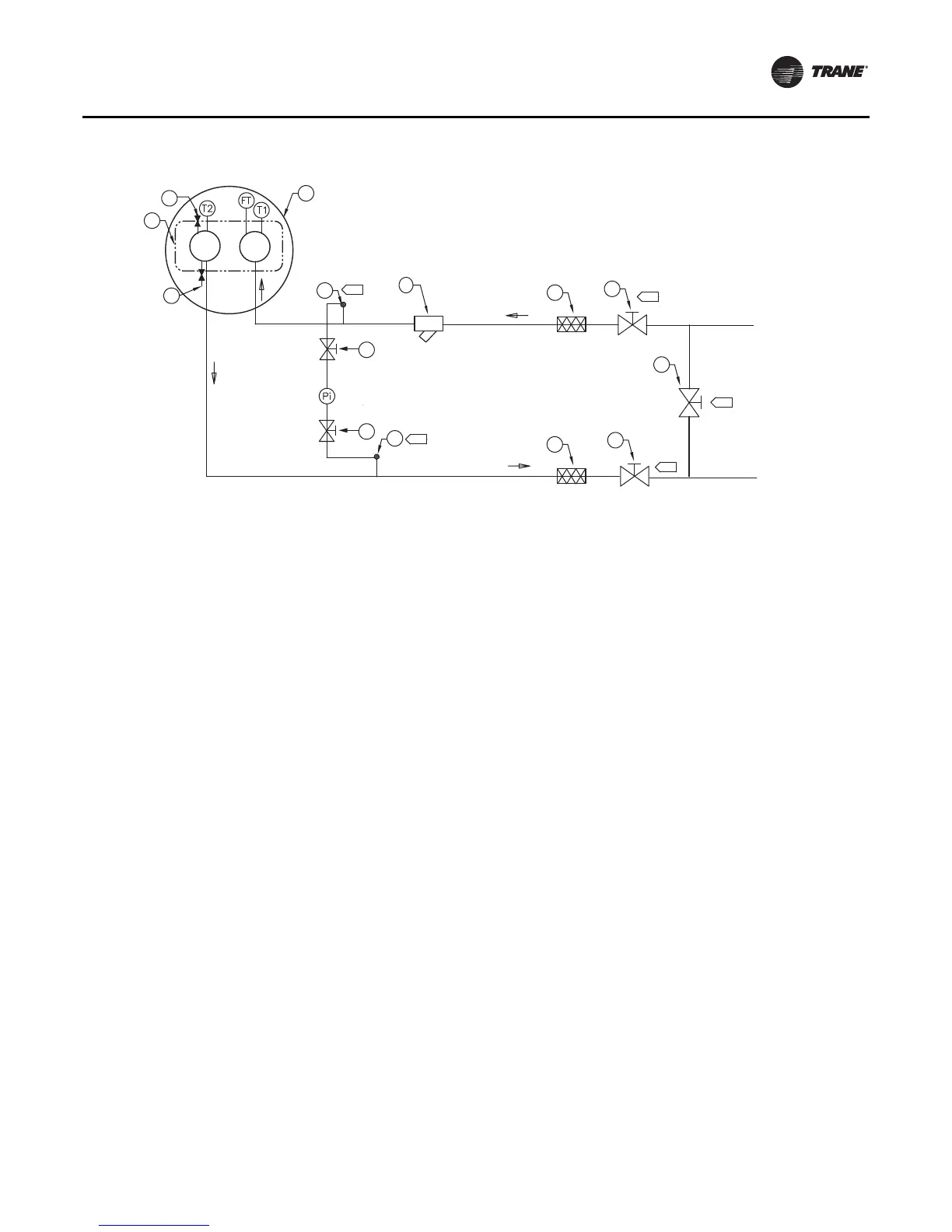
Figure 9. Evaporator water piping
1 Bypass Valve Pi Pressure Gauge
2 Isolation Valve FT Water Flow Switch
3 Vibration Isolators T1 Evaporator Water Inlet Temperature Sensor
4 Evaporator - End View (2-pass) T2 Evaporator Water Outlet Temperature Sensor
5 Evaporator Waterbox A Isolate unit for initial water loop cleaning
6 Vent B Vent must be installed at the high point of the line
7 Strainer C Drains must be installed at the low point of the line
8 Drain
A
2
1
2
3
3
7
8
6
4
5
2
2
A
A
B
8
C