Flow switch
To provide protection, install and wire flow switches in series with the water pump interlocks as required of
wiring diagrams. Flow switches must prevent or stop compressor operation if either system water flow drops
off below the required minimum shown on Table 4.General guidelines for flow switch installation are outlined
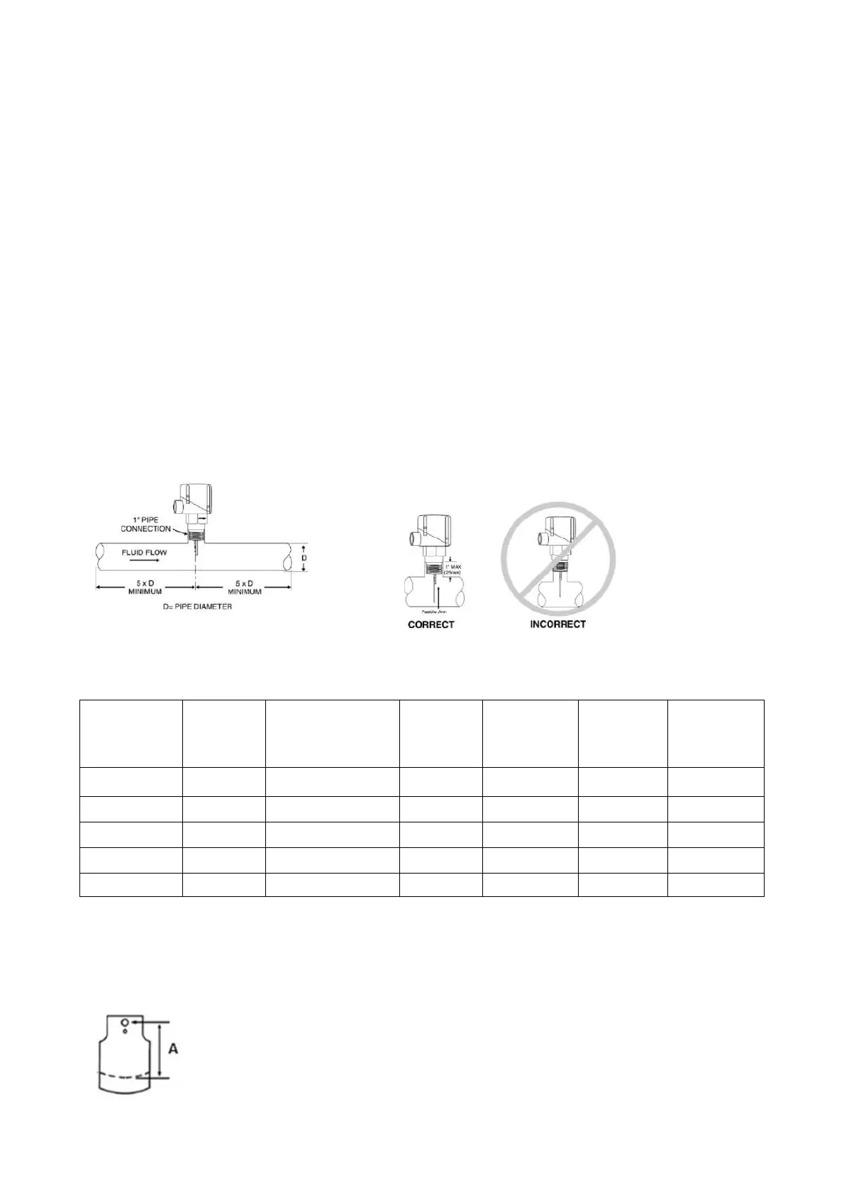
below as Figure 9 Flow switch installation.
• Mount the flow switch upright, with a minimum straight and horizontal length of 5 times its internal diameter
before and after it. Or install in a vertical pipe if the flow in the upward direction.
• Do not install close to elbows, orifices or valves.
• Refer to Table 4 Paddle Size, select and trim the paddle to the right length.
• Ensure the paddle arm extends into the main run of the pipe and the arrow on the switch mustpoint in the
direction of the
water flow after switch tighten to final position.
• To prevent switch fluttering, remove all air from the water system.
• Adjust the switch to open when water flow falls below the required minimum shown onthe pressuredrop
curves as Figure
10. Flow switch contacts are closed on proof of water flow.
• Wire flow switches in series with the water pump interlocks as in Trane wiring diagrams.
Note: Dual flow switch for assembly unit RTXC310/330/360/400/440XE, install appropriate water flow
switches at the water outlet of each unit, refer to Section of Master - slave unit.
Table 4 Paddle Size of Water Flow Switch
Model
water pipe
size
Recommended main
water pipe size
Trim to
Length
A(mm)
flow rate(L/s)
rate(L/s)
rate(L/s)
RTXC110XE DN100 > DN100 28 18
9.1 27.3
RTXC160XE DN150 > DN150 70 28
13.9 41.7
RTXC180XE DN150 > DN150 60 31
15.3 45.9
RTXC200XE DN150 > DN150 51 32
16.2 48.5
RTXC220XE DN150 > DN150 41 36
17.9 53.9
Figure 9 Flow switch installation