10
S9V2-VS-SVX001-1C-EN
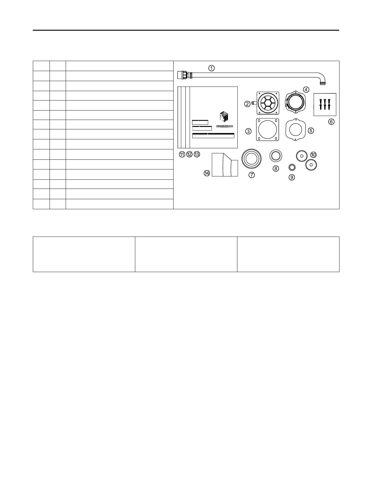
Document Pack Contents S9V2-VS
Item
Qty. Description
SSAAFFEETTYY WWAARRNNIINNGG
Onlyqualied personnelshould installand servicethe equipment.The installation,starting up,and servicingof heating,ventilating, andair-conditioning
equipmentcan behazardous andrequires specicknowledge andtraining. Improperlyinstalled, adjustedor alteredequipment byan unqualiedperson
couldresult indeath orserious injury.When workingon theequipment, observeall precautionsin theliterature andon thetags, stickers,andlabels that
areattached tothe equipment.
Upow/Horizontal and Dedicated Downow
Gas-Fired, Direct/Non-Direct Vent, 2-Stage
Condensing Variab
l
e Speed Furnac
e
s with Variab
l
e Speed
Graphics in this document are for representation
only. Actual model may differ in appearance.
Note:
CAUTION
!
Failure to follow this Caution could result in property damage or personal injury. 4GXC* and
4MXC* coils installed on upflow furnaces in vertical, horizontal left, or horizontal right
orientations without a factory installed metal drain pan shield must use a MAY*FERCOLKITAA
kit. Coils installed on upflow furnaces must have drain pans that are suitable for 400° F
(205°C) or have a metal drain pan shield. Downflow furnaces do not require a metal drain pan
shield or the use of the MAY*FERCOLKITAA kit.
COIL REQUIREMENT!
Installation, Operation, and Maintenance
Draft Inducer
UU pp ffllooww ,,CC oo nnvveerrttiibbllee ttoo
HHoorriizzoo nn ttaallRR iigghh tt oo rr
HHoorriizzoo nn ttaallLLeefftt
S9V2B040U3VSB
S9V2B060U3VSB
S9V2B080U4VSB
S9V2C100U4VSB
S9V2D120U5VSB
DDooww nnffll oo ww OO nnllyy
S9V2B060D3VSB
S9V2B080D4VSB
S9V2C100D4VSB
WARNING
FIRE HAZARD!
Failure to follow this Warning could result in property damage, severe personal
injury, or death.
This Warning applies to installations with a
ammable refrigeration system.
The furnace must be powered except for service. The furnace shall be installed
and connected according to installation instructions and wiring diagrams that
are provided with the evaporator coil.
September 2023
SS 99VV 22--VV SS -- SS VV XX 00 00 11-- 11CC --EE NN
1 1
Condensate Drain Tube Assembly
2 1
Inlet Vent (2”- ADP01586 and 3” - ADP01587)
(a)
3 1 Inlet Vent Gasket
4 1
Outlet Vent Assembly
5 1 Outlet Vent Gasket
6 6 Screws
7 1
Condensate Trap Grommet
8 1
Plug – Condensate/Gas
9 1
Plug – Electrical
10 2
Grommet – Condensate/Gas
11 1
Installation, Operation, and Maintenance
12 1 Owner Guide
13 1
Limited Warranty
14 1
2” to 3” Coupling – CPL01544
(b)
(a)
3” inlet vent supplied with S9V2D120U5VS only. 2” inlet vent supplied with all other models.
(b)
Supplied with S9V2D120U5VS only.
Part List
• Igniter
• Flame Sensor
• In-shot Burner(s)
• Gas Valve
• Inducer Assembly
• Blower Motor
• Blower Wheel
• IFC (Integrated Furnace Control)
• Pressure Switch(es)
• Main Thermal Limit
• Roll-Out Switch(es)
• Reverse Air Switch(es)
AAcccceessssoorriieess