32
S9V2-VS-SVX001-1C-EN
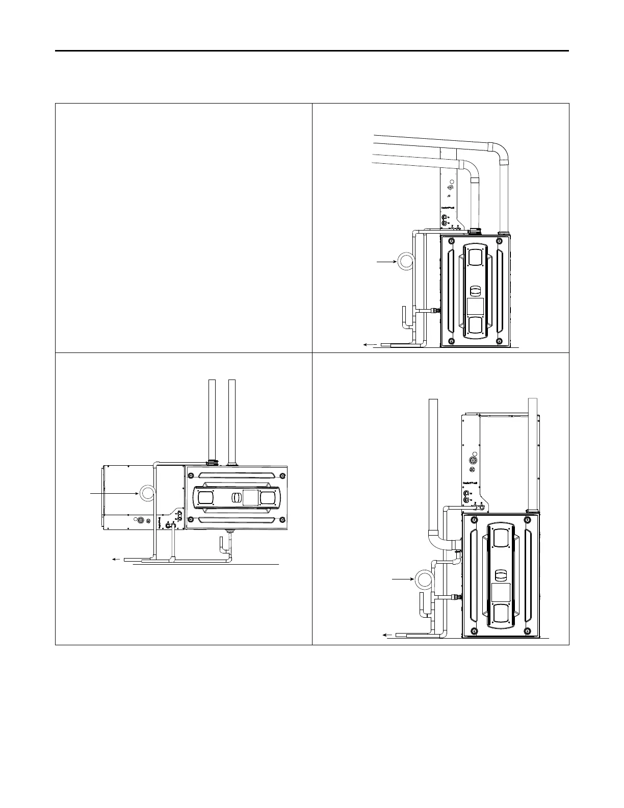
Typical Venting
This combustion air intake has a built-in condensate collection
system. Condensate that may collect is drained by field supplied 1/2"
ID tubing. The tubing must be routed to form a trap and water seal
( see Figure 1, p. 32, Figure 2, p. 32, and Figure 3, p. 32).
A field supplied hose clamp is recommended but not be required. The
tubing is not under pressure.
Combustion air piping must be square cut and de-burred for proper
drainage. For side entry combustion inlet applications, ensure the
drain is pointed downwards.
Figure 1. Upflow Top Entry
To an approved
vented drain
Combustion air
intake
Combustion air
exhaust
Slope equals 1/4” per foot
Field fabricated trap
Primary drain vent stack must
terminate below the bottom of
the condensate trap
Figure 2. Horizontal Top Entry
Combustion air
intake
Combustion air
exhaust
Field
fabricated
trap
To an approved
vented drain
Note: Primary drain vent stack must terminate below the bottom of
the condensate trap.
Figure 3. Upflow Side Entry
Combustion air
intake
Combustion air
exhaust
To an approved
vented drain
Field fabricated trap
Primary drain vent stack must
terminate below the bottom of
the condensate trap
FFuurrnnaaccee GGeenneerraall IInnssttaallllaattiioonn