EasyManua.ls Logo

Trane S9V2C100U4VSAD User Manual

Trane S9V2C100U4VSAD
120 pages
To Next Page IconTo Next Page
Page #1 background imageLoading...
Page #1 background image
SSAAFFEETTYY WWAARRNNIINNGG
Only qualified personnel should install and service the equipment. The installation, starting up, and servicing of heating, ventilating, and air-conditioning
equipment can be hazardous and requires specific knowledge and training. Improperly installed, adjusted or altered equipment by an unqualified person
could result in death or serious injury. When working on the equipment, observe all precautions in the literature and on the tags, stickers, and labels that
are attached to the equipment.
December 2022
SS99VV22--VVSS--SSVVXX000011--11BB--EENN
Upflow/Horizontal and Dedicated Downflow
Gas-Fired, Direct/Non-Direct Vent, 2-Stage
Condensing Variable Speed Furnaces with Variable Speed
Draft Inducer
UUppffllooww,, CCoonnvveerrttiibbllee ttoo
HHoorriizzoonnttaall RRiigghhtt oorr
HHoorriizzoonnttaall LLeefftt
S9V2B040U3VSAE
S9V2B060U3VSAC/D
S9V2B080U4VSAC/D
S9V2C100U4VSAC/D
S9V2D120U5VSAC/D
DDoowwnnffllooww OOnnllyy
S9V2B080D4VSAC/D
S9V2C100D4VSAC/D
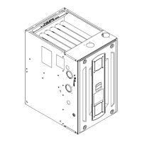
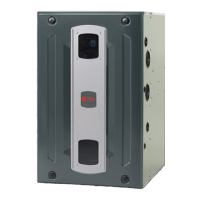
NNoottee:: Graphics in this document are for representation
only. Actual model may differ in appearance.
CAUTION
!
Failure to follow this Caution could result in property damage or personal injury. 4GXC* and
4MXC* coils installed on upflow furnaces in vertical, horizontal left, or horizontal right
orientations without a factory installed metal drain pan shield must use a MAY*FERCOLKITAA
kit. Coils installed on upflow furnaces must have drain pans that are suitable for 400° F
(205°C) or have a metal drain pan shield. Downflow furnaces do not require a metal drain pan
shield or the use of the MAY*FERCOLKITAA kit.
COIL REQUIREMENT!
S9V2-VS-SVX001-1B-EN
Installation, Operation, and Maintenance
Question and Answer IconNeed help?

Do you have a question about the Trane S9V2C100U4VSAD and is the answer not in the manual?

Trane S9V2C100U4VSAD Specifications

General IconGeneral
BrandTrane
ModelS9V2C100U4VSAD
CategoryFurnace
LanguageEnglish

Summary

Installation, Operation, and Maintenance

Safety Section — Furnaces

Fire, Explosion, and Electrical Hazards

Critical warnings about fire, explosion, and electrical shock risks.

Chemical Exposure and Installation Hazards

Covers chemical exposure, electrical shock, and specific installation hazards.

Installation and Component Safety Warnings

Warnings related to high voltage, moving parts, filters, and electrical shock.

Electrical and Environmental Cautions

Cautions regarding voltage connection, corrosive atmospheres, and venting termination.

Surface, Service, and Construction Safety

Safety warnings for hot surfaces, furnace servicing, and use as a construction heater.

Carbon Monoxide Hazards

Warnings about carbon monoxide poisoning risks and proper venting.

Propane Gas and General Safety

Warnings for propane gas and general safety hazards.

Venting and Overheating Hazards

Warnings about venting system safety and overheating hazards.

Venting System Safety

Critical safety instructions for operating the venting system.

Furnace Installation Guidelines

Safety Practices and Precautions

Essential safety steps and precautions for furnace installation.

Furnace General Installation

Gas Valve Adjustment

Steps for adjusting manifold pressure for gas valve operation.

General Venting

Requirements and guidelines for furnace venting systems.

Air for Combustion and Ventilation

Requirements for adequate airflow for combustion and ventilation.

Gas Piping

Detailed instructions for connecting the gas supply to the furnace.

Combustion and Input Check

Procedure for verifying proper gas combustion and input rate.

Electrical Connections

Field Wiring

Diagrams and notes for field wiring thermostat and outdoor unit connections.

Condensate Drain Instructions

Water Damage/Property Damage!

Warnings about potential water damage from condensate.

General Start-up and Adjustment

Control and Safety Switch Adjustment

Checking and adjusting limit switches for safe operation.

Integrated Furnace Control Menu

Control System Menu

Navigation and options for the furnace control system menu.

Integrated Furnace Control Display Codes

Table of display codes and their meanings for fault recovery.

Troubleshooting

Error Codes and IFC Layout

Table of error codes and diagram of IFC components.

2.2 Fault Code

Troubleshooting flowchart for flame sensing and gas pressure issues.

3.2 Fault Code

Troubleshooting flowchart for PS2 pressure switch orientation and voltage issues.

Getting Started Diagnostics

Initial diagnostic steps and flowcharts for troubleshooting.

3.1 Fault Code

Troubleshooting flowchart for PS1 pressure switch errors.

3.3 Fault Code

Troubleshooting flowchart for PS2 pressure switch orientation errors.

Ignition and Gas Pressure Faults

Troubleshooting for ignition and gas pressure issues.

3.4 Fault Code

Troubleshooting flowchart for PS2 pressure switch voltage and motor issues.

Sequence of Operation

Related product manuals