EasyManua.ls Logo

Trane Stealth RTAE - User Manual

Trane Stealth RTAE
24 pages
Print Icon
To Next Page IconTo Next Page
Loading...
Stealth™ Model RTAE Chillers
Field Replacement of GP4 Classic
Compressor
Installation Instructions
April 2022
PART-SVN237B-EN
SAFETY WARNING
Only qualified personnel should install and service the equipment. The installation, starting up, and servicing of
heating, ventilating, and air-conditioning equipment can be hazardous and requires specific knowledge and training.
Improperly installed, adjusted or altered equipment by an unqualified person could result in death or serious injury.
When working on the equipment, observe all precautions in the literature and on the tags, stickers, and labels that are
attached to the equipment.
Question and Answer IconNeed help?

Do you have a question about the Trane Stealth RTAE and is the answer not in the manual?

Overview

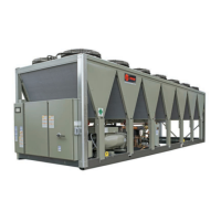
This document outlines the installation instructions for the field replacement of GP4 Classic Compressors in Trane Stealth™ Model RTAE Chillers. It serves as a comprehensive guide for qualified personnel, emphasizing safety, proper procedures, and necessary adaptations for a successful compressor replacement.

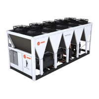
The core function of this document is to provide detailed steps and information for replacing a failed 1st or 2nd Generation GP4 Classic Compressor with a GP4 VarVi Service Compressor in RTAE Chillers. This replacement is necessary because the Classic chassis has been discontinued. The service model GP4 VarVi Compressor is designed to perform similarly to the classic GP4 compressor through specific adaptations.

Key usage features include:

  • Compressor Replacement Guidance: The manual provides a cross-list (Table 2) to identify the correct VarVi GP4 Service Model compressor based on the original GP4 Screw Compressor's capacity, lift, voltage, and motor number (MN). This ensures that the correct replacement unit is selected.
  • Identification of Additional Parts: A crucial aspect of the replacement process is the identification and ordering of additional parts, as only the compressor is delivered as standard. The document details how to determine these parts by referencing the unit's nameplate and compressor motor nameplate. This includes specific instructions for ordering heaters (Table 3), terminal boxes (Table 4), sound attenuators (Table 5), and suction/discharge gaskets.
  • Handling of Output Inductors (1st Gen GP4 Classic Compressor Only): For 1st Generation GP4 Classic Compressors, the document provides explicit instructions for the physical removal of output inductors from each circuit. This involves disconnecting thermal cutout limit switch connections and splicing power conductors together using recommended insulated in-line splice connectors. Electrical schematics (Figure 3 and Figure 4) are provided to illustrate these connections, along with a visual guide to output inductor locations (Figure 5).
  • Adding Common Mode Chokes (1st Gen GP4 Classic Compressor Only): This section details the necessity of adding common mode chokes to maintain protection against bearing currents, especially after the removal of output inductors. It explains that the choke assembly encircles all current-carrying conductors between the drive and compressor. The document specifies the quantity and mnemonic for ordering common mode core assemblies and individual conductor cores (Table 7), and includes an electrical schematic (Figure 8) and an image (Figure 9) showing their locations.
  • Reprogramming AFD3: After compressor replacement, reprogramming the AFD3 (Adjustable Frequency Drive) is essential. The manual outlines a high-level process for this, including navigating the binding process, unbinding the appropriate circuit AFD3 drive, accessing the Config screen in TU software, changing required parameters, and rebinding the AFD3. It also provides a detailed table (Table 8) with programming values for the AFD3 drive, categorized by GP4 VarVi Service Model Number and specific parameters like Motor Type, Transformer Input Ratio, Total System Inertia, Motor NP Volts, Motor NP RLA Current, Motor NP Power, Motor NP Number of Poles, Motor NP RPM, and Motor NP Magnet Flux. Special attention is given to parameter updates required for 1st Generation units, noting that some units may experience a small reduction in top-end operational capacity due to differences in motor performance and AFD3 size.
  • Piping and Fitting Modifications: The document acknowledges that piping and fitting changes may be required and advises sourcing these locally. It also emphasizes the importance of installing field-installed insulation before adding refrigerant for proper adhesion.
  • Installation Procedure Visual Aids: The manual includes several figures to aid in the installation process, such as the compressor terminal box (Figure 11), cartridge heater location (Figure 12), band heater location (Figure 13), high pressure switch location (Figure 14), intermediate oil pressure transducer location (Figure 15), solenoid stems (Figure 16), and various piping modifications (Figure 17, Figure 18, Figure 19, Figure 20, Figure 21, Figure 22). These visuals help technicians understand the physical aspects of the installation.

Maintenance features are implicitly covered through the detailed installation and reprogramming instructions, ensuring the longevity and proper functioning of the replaced compressor. By following these guidelines, technicians can ensure that the new compressor operates efficiently and reliably within the chiller system. The emphasis on ordering specific parts and reprogramming the AFD3 correctly contributes to the overall maintainability and performance of the unit post-replacement. The document also highlights the importance of observing all safety precautions, wearing proper Personal Protective Equipment (PPE), and adhering to environmental concerns related to refrigerant handling, which are crucial aspects of safe and responsible maintenance practices.

Trane Stealth RTAE Specifications

General IconGeneral
EfficiencyHigh Efficiency
Full Load Efficiency (kW/Ton)0.70
Operating Voltage460V
Water Flow Rate (GPM)Varies with model, consult factory
Dimensions (L x W x H, in)Varies with model, consult factory
Sound Level72 - 82 dBA

Related product manuals