18-GJ05D1-12A-EN
ALL phases of this installation must comply with NATIONAL, STATE AND LOCAL CODES
Important: This Document is customer property and is to remain with this unit. Please return to service information
pack upon completion of work.
Important: These instructions do not cover all variations
in systems nor provide for every possible contingency to
be met in connection with the installation. Should further
information be desired or should particular problems
arise which are not covered sufficiently for the pur-
chaser’s purposes, the matter should be referred to your
installing dealer or local distributor.
Note: The manufacturer recommends installing ONLY
AHRI approved, matched indoor and outdoor systems.
Some of the benefits of installing approved matched
indoor and outdoor split systems are maximum efficien-
cy, optimum performance, and the best overall system
reliability.
Note: All AHRI ratings use a 90 second fan off delay.
Use your branded thermostat or separate relay to enable
this delay.
Note: Condensation may occur on the surface of the air
handler when installed in an unconditioned space. When
units are installed in unconditioned spaces, verify that
all electrical and refrigerant line penetrations on the air
handler are sealed completely.
Important: TAM4A0C60S51 air handler applied in
downflow or horizontal configurations should not exceed
2000 CFM. Airflow above 2000 CFM could result in
water blow-off. For verification, see airflow table.
Important: The TAM4 air handlers will only use the fol-
lowing internal electric heaters:
BAYEAAC04BK1, BAYEAAC04LG1
BAYEAAC05BK1, BAYEAAC05LG1
BAYEAAC08BK1, BAYEAAC08LG1
BAYEAAC10BK1, BAYEAAC10LG1
BAYEAAC10LG3, BAYEABC15BK1
BAYEABC15LG3, BAYEABC20BK1
BAYEACC25BK1
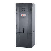
Convertible Air Handlers
1-1/2 – 5 Ton
Black Epoxy Coil
TAM4A0A18S11ED
TAM4A0A24S21ED
TAM4A0A30S21ED
TAM4A0A36S31ED
TAM4A0B42S31ED
TAM4A0C48S41ED
TAM4A0C60S51ED
Installer’s Guide
Standard Coil
TAM4A0A18S11SD
TAM4A0A24S21SD
TAM4A0A30S21SD
TAM4A0A36S31SD
TAM4A0B42S31SD
TAM4A0C48S41SD
TAM4A0C60S51SD
Note: Representative illustrations only included
in this document. Most illustrations display the
upflow configuration.