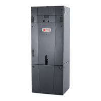
Do you have a question about the Trane TAM4A0A24S21SB and is the answer not in the manual?
Requirements and safety warnings for field wiring and grounding.
Procedure for inspecting the air handler upon receipt for completeness and damage.
Instructions for handling and reporting shipping damage.
Procedures for removing shipping tie-downs and general lifting considerations.
Instructions for removing shipping tie-downs prior to unit placement.
Safety warnings and procedures for lifting heavy objects and units.
Procedures for placing and assembling units shipped in sections.
Important considerations for placing the unit, including temperature limits.
Information on assembling unit sections and using mounting frames.
Steps for joining multiple unit sections together.
Requirements for seismic response criteria compliance.
Specifications for anchoring units to the roof or floor.
Standards and guidelines for connecting ducts to air handlers.
Instructions for installing filters, including safety warnings for hazardous voltage.
Proper installation, piping, and trapping for satisfactory coil operation.
Guidelines for proper drain pan trapping and condensate drainage.
Information on handling refrigerants and component placement.
Sizing, routing, and insulation requirements for liquid lines.
Sizing, routing, and insulation requirements for suction lines.
Diagram and instructions for single-circuit evaporator coil piping.
Diagram and instructions for single-circuit evaporator coil piping with two distributors.
Diagram and instructions for single-circuit evaporator coil piping with four distributors.
Diagram and instructions for dual-circuit evaporator coil piping.
Diagram and instructions for dual-circuit evaporator coil piping.
Diagram and instructions for dual-circuit evaporator coil piping.
Requirements for high voltage power supply and compliance with codes.
Steps for routing high voltage wiring and selecting conduit entry points.
Checklist to complete before operating the air handler.
Ensuring the unit is installed level and all connections are made.
Inspecting fan wheels, bearings, and drive components.
Ensuring proper water treatment and checking for leaks.
Verifying motor lubrication, winding resistance, and rust.
Safety warnings for rotating and live electrical components.
Instructions for proper fan belt tensioning and adjustment.
Procedure for aligning fan and motor sheaves using a straightedge.
Information on Traq dampers, VCM calibration, and airflow calculations.
A guide to identifying probable causes and corrective actions for air handler issues.
Abbreviated guide to periodic maintenance tasks for the air handler.
Procedures for cleaning or replacing throwaway, permanent, and bag filters.
Safety warnings and procedures for cleaning drain pans.
Instructions for inspecting and cleaning fan sections.
Six-month inspection of fan sections for microbial growth and cleaning procedures.
Safety warnings and procedures for cleaning steam and water coils.
Safety warnings for hazardous pressures and chemicals when cleaning coils.
Guidelines for connecting ductwork, including sealing and insulation.
Step-by-step instructions for brazing refrigerant line connections.
Guidelines for condensate drain plumbing, including slope and fittings.
Steps to connect condensate drain piping for different unit orientations.
Steps for routing high voltage wiring and making electrical connections.
Steps for safely starting up the system, including thermostat settings.
Detailed sequence of operation for various modes: Continuous Fan, Heatpump OD, Electric Heating.
A checklist for verifying system operation and performance after installation.
Verifying control module installation and wiring for cooling units.
Verifying control module installation and wiring for heat pump units.
Critical safety warnings for electrical, thermal, and mechanical hazards.
Guidelines for pump support, installation location, and vibration isolation.
Wiring diagrams for single and three-phase motors.
Critical warnings regarding power connections and wiring.
Minimum clearances required between damper sleeves and openings.
Instructions for attaching damper/sleeve assemblies using retaining angles.
Common damper issues and their corrective actions.
| Model | TAM4A0A24S21SB |
|---|---|
| Type | Air Handler |
| Refrigerant | R-410A |
| Voltage | 208/230V |
| Phase | 1 |
| Maximum Overcurrent Protection | 15A |
| Shipping Weight | 95 lbs |
| Cooling Capacity | 2 Tons |
| Airflow Range | 400-1200 CFM |


