6
18-GF75D1-1C-EN
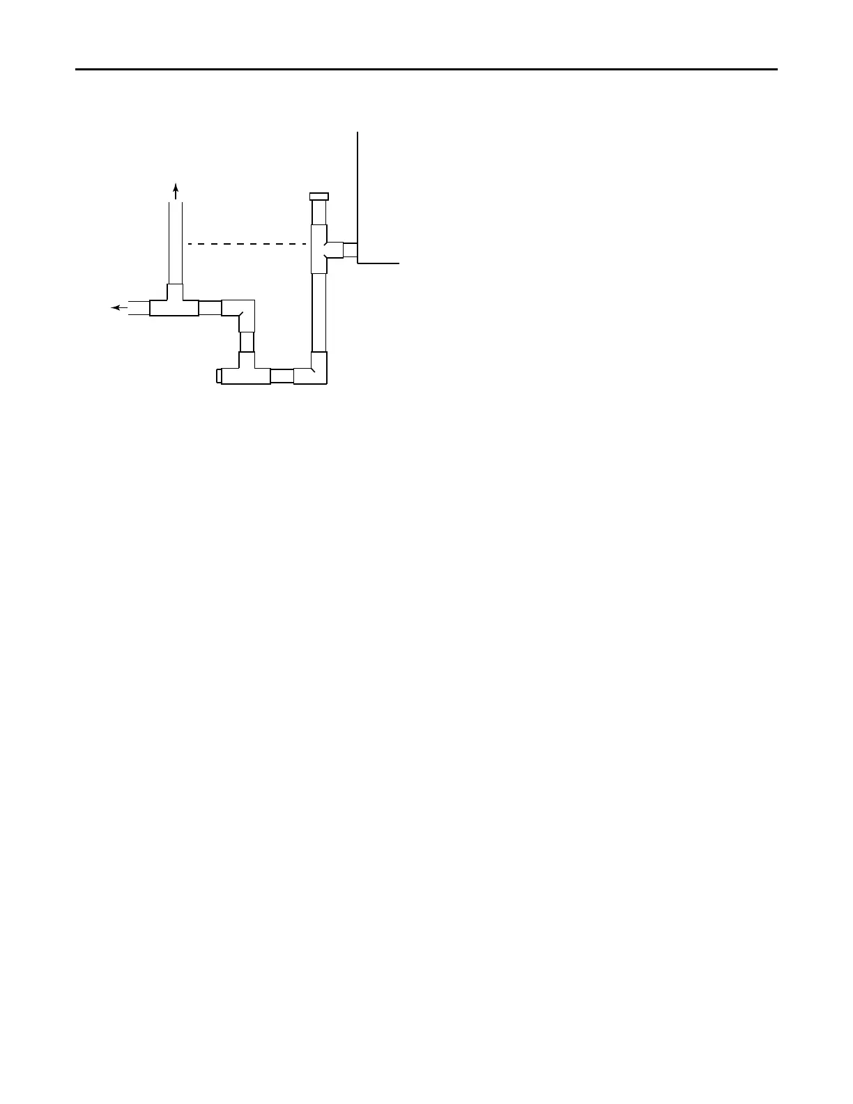
To Drain
Vent
-This vent pipe MUST
terminate above the
dotted line
Cleanout
(with Cap)
Cleanout
(Plug)
Insulate the primary drain line to prevent sweating
where dew point temperatures may be met.
(Insulation is optional depending on climate and
application needs.)
5. RReeffrriiggeerraanntt PPiippiinngg
Refrigerant piping external to the unit shall be sized
in accordance with the instructions of the
manufacturer of the outdoor equipment.
6. MMeetteerriinngg DDeevviiccee
All units are shipped and installed with an
internally-checked, bleed TXV designed for air
conditioning or heat pump operation. Pressures
equalize after shut down. Some outdoor models
may require a start assist kit. See outdoor unit for
more information.
7. BBlloowweerr
This unit is supplied with a multi-speed motor with
a direct drive blower wheel which can obtain
various air flows. The unit is shipped with factory
set cooling and heating speed taps. Airflow
performance tables are available for additional
speed taps. Disconnect all power to the unit before
making any adjustments to the motor speed taps.
Be sure to check the air flow and the temperature
drop across the evaporator coil to ensure sufficient
air flow.
8. WWiirriinngg
Consult all schematic and pictorial wiring diagrams
of this unit and the outdoor equipment to
determine compatibility of wiring connections and
to determine specific requirements.
All field wiring to the air handler should be installed
in accordance with the latest edition of the National
Electric Code NFPA No. 70 and any local codes.
Check rating plates on unit for rated volts,
minimum circuit ampacity and maximum over
current protection. Supply circuit power wiring
must be 75 degree C (167 degree F) minimum
copper conductors only. Copper supply wires shall
be sized to the National Electric Code or local code
requirements, whichever is more stringent.
The unit is shipped wired for 230/240 Volt AC 60 HZ
1 Phase Operation. If the unit is to be operated at
208 VAC 60HZ, follow the instructions on the indoor
unit wiring diagram to change the low voltage
transformer to 208 VAC operation (Ensure unit is
properly grounded).
Class 2 low voltage control wiring should not be run
in conduit with power wiring and must be
separated from power wiring unless class 1 wire
with proper voltage rating is used.
Low voltage control wiring should be 18 Awg, color
coded (105 degree C minimum). For lengths longer
than 100ft., 16 Awg wire should be used. Make
certain that separation of control wiring and power
wiring has been maintained.
9. AAiirr FFiilltteerr
To protect the coil, blower and other internal parts
from excessive dirt and dust an air filter must be
installed before air enters the evaporator coil. A
remote filter must be installed. Consult the filter
manufacturer for proper sizing and maximum
velocity requirements.
10. TThheerrmmoossttaatt
Select a thermostat that is commonly used with HP
or AC single stage heating/cooling with electric
heat. The thermostat will energize the fan on a
demand for heat or cool.
Install the thermostat on an inside wall, away from
drafts, lights or other heat sources in a location that
has sufficient air circulation from other rooms being
controlled by the thermostat.
11. SSeeqquueennccee ooff OOppeerraattiioonn
CCoooolliinngg ((CCoooolliinngg oonnllyy))
When the thermostat calls for cooling, the circuit
from R to G is completed. The blower motor is
energized directly by the 24VAC signal from the
thermostat.
The circuit from R to Y is also complete energizing
the compressor contactor of the outdoor unit. The
contactor will close and start the compressor and
condenser fan motor.
CCoooolliinngg ((hheeaatt ppuummpp))
When the thermostat calls for cooling, the circuit
from R to G is completed. The blower motor is
energized directly by the 24VAC signal from the
thermostat.
The circuit from R to Y is also complete energizing
the compressor contactor of the outdoor unit. The
contactor will close and start the compressor and
condenser fan motor.
IInnssttaallllaattiioonn IInnssttrruuccttiioonnss