Home
Trane
Air Handlers
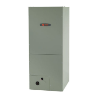
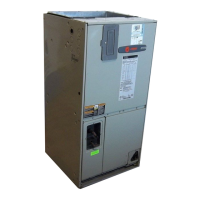
TEM4 Series
Trane TEM4 Series User Manual
5
of 1
of 1 rating
24 pages
Give review
Manual
Specs
To Next Page
To Next Page
To Previous Page
To Previous Page
Loading...
8
18-GF75D1-1C-EN
Field
Wiring
and
Electrical
Data
Figure
1.
Field
Wiring
Diagrams
R
G
B
W1
W2
R
B
O
Y
X2
R
G
B/C
O
Y
W
HEA
T PUMP SYSTEMS
Blue
24 V
AC HOT
F
AN
24 V
AC
Common
SOV
COOL/HEA
T
1st ST
AGE
HEA
TING
2nd ST
AGE
EMERGENCY
HEA
T
Thermostat
Air Handler
Outdoor
Unit
Pink
Black
W2
Pink
White
White
X2
AC SYSTEMS
R
G
B
W1
B
Y
R
G
B/C
Y
W
Blue
24 V
AC HOT
F
AN
24 V
AC
Common
COOLING
HEA
T
Thermostat
Air Handler
Outdoor
Unit
In
AC systems for multiple stages of electric heat, jumper W1
and W2 together if comfort control has only one stage of heat.
Figure
2.
Electrical
Wiring
Diagram
(All
models)
7
9
Table of Contents
Table of Contents
4
Installation Instructions
5
Field Wiring and Electrical Data
8
Performance and Electrical Data
9
Minimum Airflow CFM
14
Outline Drawing
15
Heater Pressure Drop Table
16
Coil Conversion Instructions
17
Checkout Procedures
24
5
Based on 1 rating
Ask a question
Give review
Questions and Answers:
Need help?
Do you have a question about the Trane TEM4 Series and is the answer not in the manual?
Ask a question
Trane TEM4 Series Specifications
General
Type
Air Handler
Series
TEM4
Refrigerant
R-410A
Motor Type
PSC or ECM
Cabinet Type
Upflow, Downflow, Horizontal
Dimensions
Varies by model
Weight
Varies by model
Related product manuals
Trane TEM6A0B30H21SC
32 pages
Trane TEM6A0C48H41SC
32 pages
Trane TEM6B0C60H51SA
32 pages
Trane TEM4A0C43M41SB
24 pages
Trane TEM4A0C48S41SC
24 pages
Trane TEM4A0C49M41SB
24 pages
Trane TEM4B0C60S51SA
24 pages
TEM4B0B24M21SA TEM4A0B31M31SB
24 pages
Trane TWE030CA
32 pages
Trane TWJ020-036CA
32 pages
Trane TWE031E13FB1
12 pages
Trane TAM4A0A36S31SB
251 pages