Introduction
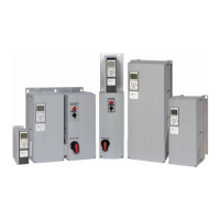
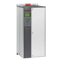
The pedestal is used to allow airow into the F-size enclosure to provide proper cooling. These instructions detail the mounting of
an F-size enclosure enclosure onto a pedestal.
More installation information, such as ambient conditions, cooling requirements, and dimensions can be found in the operating
instructions, design guide, and installation drawings.
Safety Instructions
Discharge Time
WARNING
Hazardous Voltage w/Capacitors!
Failure to disconnect power and discharge capacitors before servicing could result in death or serious injury.
Disconnect all electric power, including remote disconnects and discharge all motor start/ run capacitors before servicing.
Follow proper lockout/tagout procedures to ensure the power cannot be inadvertently energized. For variable frequency drives
or other energy storing components provided by Trane or others, refer to the appropriate manufacturer’s literature for
allowable waiting periods for discharge of capacitors. Verify with an appropriate voltmeter that all capacitors have discharged.
For additional information regarding the safe discharge of capacitors, see PROD-SVB06AEN.
The frequency converter contains DC-link capacitors, which can remain charged even when the frequency converter is not powered.
High voltage can be present even when the warning indicator lights are
o.
Failure to wait for a minimum of 40 minutes after
power has been removed before performing service or repair work can result in death or serious injury.
1. Stop the motor.
2. Disconnect AC mains and remote DC-link supplies, including battery back-ups, UPS, and DC-link connections to other
frequency converters.
3. Disconnect or lock PM motor.
4. Wait 40 minutes for the capacitors to discharge.
5. Before performing any service or repair work, use an appropriate voltage measuring device to make sure that the
capacitors are fully discharged.
Positioning the Pedestal
1. Place the pedestal in the desired location, paying attention to the following:
•
Ambient conditions
•
Cooling requirements
•
Unit dimensions and door clearances
2. Pull the mains and motor cables up through the pedestal.
3. Bolt the pedestal to the oor.
All rights reserved.
BAS-SVN021B-EN

 Loading...


