CG-SVU007C-GB
5
11UNT-PRC002-GB
Sound power levels
Discharge
Measurement conditions:
Measurements taken in a room adjacent to the room containing the FWD, at the outlet of the rectangular duct (1.5 m
long) fixed to its discharge opening.
Fan Power level in dB(A), per Hz frequency band Overall power
Unit speed 125 250 500 1000 2000 4000 8000 dB(A)
1 55 50 42 37 37 31 30 46
FWD 08 2 57 54 47 40 30 38 40 50
3 58 57 50 42 32 40 43 53
1 57 51 45 42 34 33 28 48
FWD 10 2 58 54 48 45 38 39 35 51
3 60 58 50 48 40 42 39 54
1 57 51 45 42 34 33 28 48
FWD 12 2 58 54 48 45 38 39 35 51
3 60 58 50 48 40 42 39 54
1 56 62 50 48 39 38 36 56
FWD 14 2 61 66 55 53 47 46 45 60
3 63 69 58 56 50 50 49 63
1 57 63 51 49 40 39 37 57
FWD 20 2 61 66 55 53 47 46 45 60
3 63 69 58 56 50 50 49 63
Intake
Measurement conditions:
Measurements taken at the horizontal air intake.
Fan Power level in dB(A), per Hz frequency band Overall power
Unit speed 125 250 500 1000 2000 4000 8000 dB(A)
1 56 55 55 53 46 45 42 57
FWD 08 2 63 62 60 60 53 53 53 64
3 66 65 63 62 56 55 57 67
1 62 58 55 58 51 48 44 61
FWD 10 2 66 63 60 62 56 55 52 66
3 70 67 63 65 59 59 57 69
1 62 58 55 58 51 48 44 61
FWD 12 2 66 63 60 62 56 55 52 66
3 70 67 63 65 59 59 57 69
1 66 65 65 65 57 50 46 68
FWD 14 2 73 72 69 71 64 59 57 74
3 78 76 73 75 69 64 63 78
1 68 72 64 64 56 52 50 69
FWD 20 2 76 76 68 71 65 61 61 75
3 78 79 71 74 69 66 66 78
Important note: This document describes all the
functions available on TRACER CH535 with software
version 1.x and explains how to program it. Certain
parameters must only be modified by qualified
personnel. Before changing any parameter, always
check that the change does not affect the good and safe
operation of the equipment.
Operation must always stay within the catalogued limits.
Tracer CH535 is a programmable microprocessor
electronic controller dedicated to handle safe and
optimized operation of the scroll compressor chiller,
series Conquest, only cooling (CGAX) and heat pumps
(CXAX).
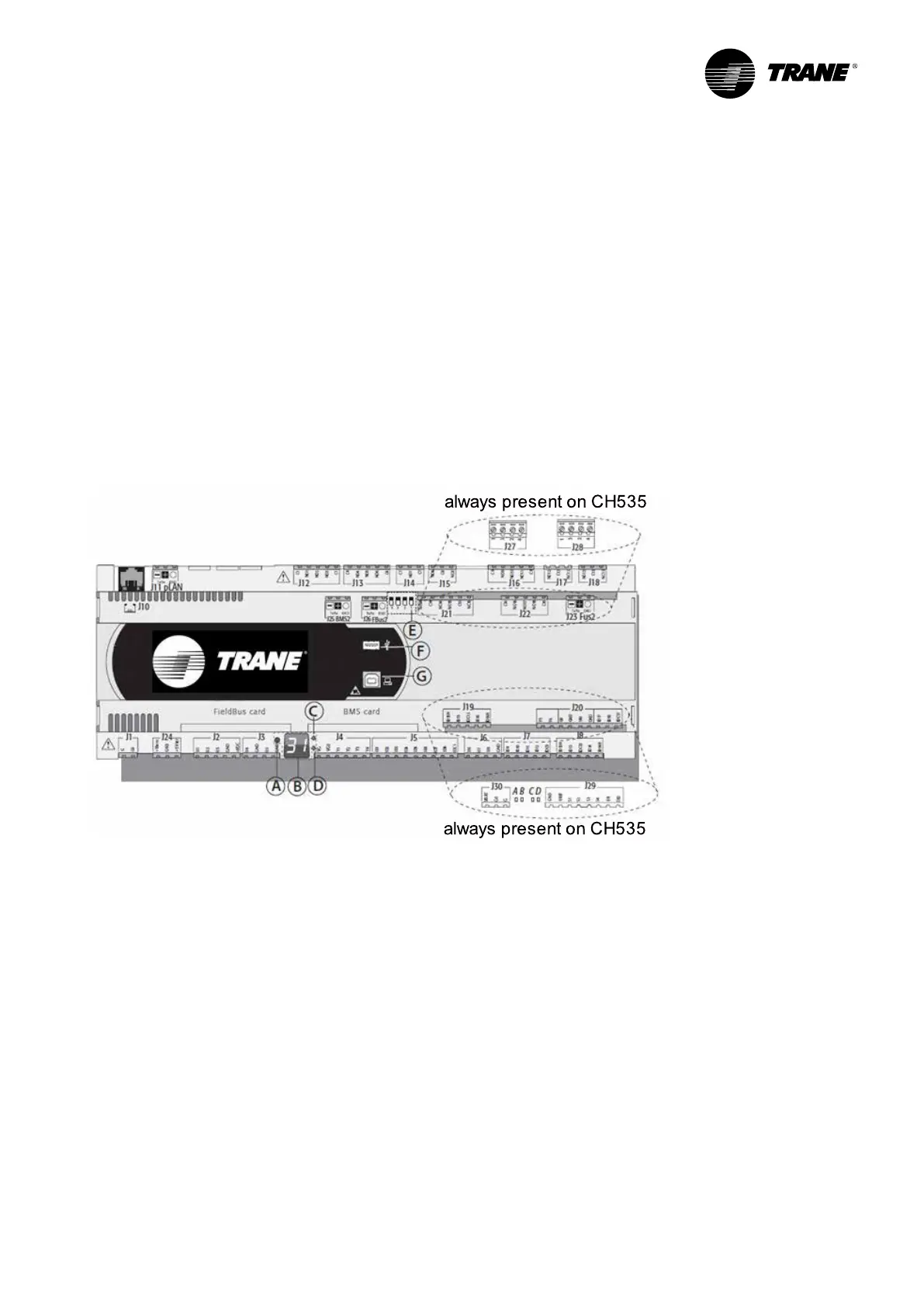
Module description
Figure 1 – Programmable microprocessor electronic
controller
A = pLAN Address selection key
B = pLAN Address display
C = Power Supply Presence LED
D = Overcharge LED
E = Fieldbus/BMS on port J26 micro switch
F = USB host (master ) port
G = USB slave (device) port
Each controller is provided with connectors for the
inputs/output and the pLAN address display, which has a
button and a LED for setting the pLAN address.
Tracer CH535 Presentation
 Loading...


