CG-SVU007C-GB
9
11UNT-PRC002-GB
Sound power levels
Discharge
Measurement conditions:
Measurements taken in a room adjacent to the room containing the FWD, at the outlet of the rectangular duct (1.5 m
long) fixed to its discharge opening.
Fan Power level in dB(A), per Hz frequency band Overall power
Unit speed 125 250 500 1000 2000 4000 8000 dB(A)
1 55 50 42 37 37 31 30 46
FWD 08 2 57 54 47 40 30 38 40 50
3 58 57 50 42 32 40 43 53
1 57 51 45 42 34 33 28 48
FWD 10 2 58 54 48 45 38 39 35 51
3 60 58 50 48 40 42 39 54
1 57 51 45 42 34 33 28 48
FWD 12 2 58 54 48 45 38 39 35 51
3 60 58 50 48 40 42 39 54
1 56 62 50 48 39 38 36 56
FWD 14 2 61 66 55 53 47 46 45 60
3 63 69 58 56 50 50 49 63
1 57 63 51 49 40 39 37 57
FWD 20 2 61 66 55 53 47 46 45 60
3 63 69 58 56 50 50 49 63
Intake
Measurement conditions:
Measurements taken at the horizontal air intake.
Fan Power level in dB(A), per Hz frequency band Overall power
Unit speed 125 250 500 1000 2000 4000 8000 dB(A)
1 56 55 55 53 46 45 42 57
FWD 08 2 63 62 60 60 53 53 53 64
3 66 65 63 62 56 55 57 67
1 62 58 55 58 51 48 44 61
FWD 10 2 66 63 60 62 56 55 52 66
3 70 67 63 65 59 59 57 69
1 62 58 55 58 51 48 44 61
FWD 12 2 66 63 60 62 56 55 52 66
3 70 67 63 65 59 59 57 69
1 66 65 65 65 57 50 46 68
FWD 14 2 73 72 69 71 64 59 57 74
3 78 76 73 75 69 64 63 78
1 68 72 64 64 56 52 50 69
FWD 20 2 76 76 68 71 65 61 61 75
3 78 79 71 74 69 66 66 78
TRACER CH535 offers customer the possibility to use
inputs or outputs in order to:
• use an external water setpoint reset using an analog
input (option),
• use an auxiliary setpoint (option),
• connect a remote on/off of the circuit/unit (standard),
• connect a remote Cooling/Heating switch (standard),
• return a circuit fault (option),
• receive unit capacity percent (option).
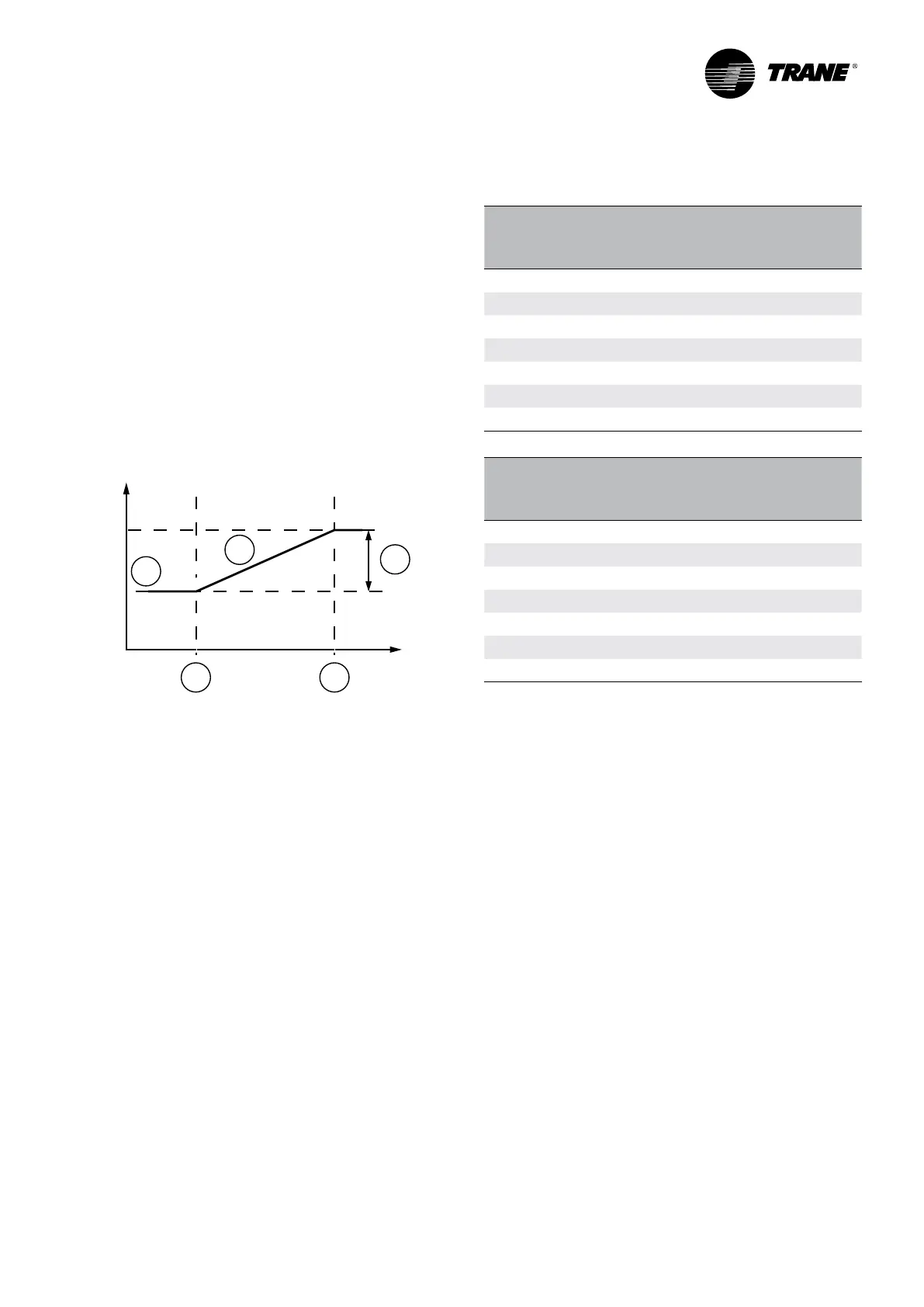
Note: External water setpoint based on an external
signal input (0-20mA or 4-20mA), it will be possible to
offset the active setpoint from 0°C to 20°C. This function
can be used in conjunction with the automatic setpoint
reset function.
5
1
4
2 3
1 = Leaving water temperature setpoint
2 = Minimum value
3 = Maximum value
4 = Reset = 20°C
5 = Active setpoint
Note: External demand limit setpoint based on an
external signal input (0-20mA or 4-20mA), it will define
the number of compressors allowed to start.
Table 3 – External demand limit setpoint allowances
Nb of CMP allowed
Percent
Current
0-20mA
Simplex
Duo
Simplex
Trio
Duplex
0.0% 0 1 1 1
25.0% 5 1 1 2
33.3% 6.66 1 2 2
50.0% 10 2 2 3
66.7% 13.34 2 3 3
75.0% 15 2 3 4
100.0% 20 2 3 4
Nb of CMP allowed
Percent
Current
4-20mA
Simplex
Duo
Simplex
Trio
Duplex
20.0% 4 1 1 1
40.0% 8 1 1 2
46.7% 9.33 1 2 2
60.0% 12 2 2 3
73.4% 14.67 2 3 3
80.0% 16 2 3 4
100.0% 20 2 3 4
Tracer CH535 module connections Terminals
Water setpoint
Ambient
temperature
 Loading...


