CNT-SVX08F-EN 39
PID Control
Example 2
A supply fan controls the static pressure in ductwork supplying variable-air-volume (VAV) boxes.
The supply fan operates at its highest speed if the PID output is at 100% (when the pressure is too
low). If the pressure goes above the setpoint, the supply fan should slow down to blow less air to
the VAV boxes. So if the process variable (the pressure) increases, the variable-frequency drive
(VFD) decreases the fan speed. Since the process variable and the control signal to the VFD move
in opposite directions, the PID loop is reverse acting.
Error Deadband
Error deadband is typically used to minimize actuator activity. It can also be used to allow for some
“slop” in the system sensors and actuator mechanics. Error deadband prevents the PID output
from changing if the absolute value of the error is less than the error deadband. For example, in
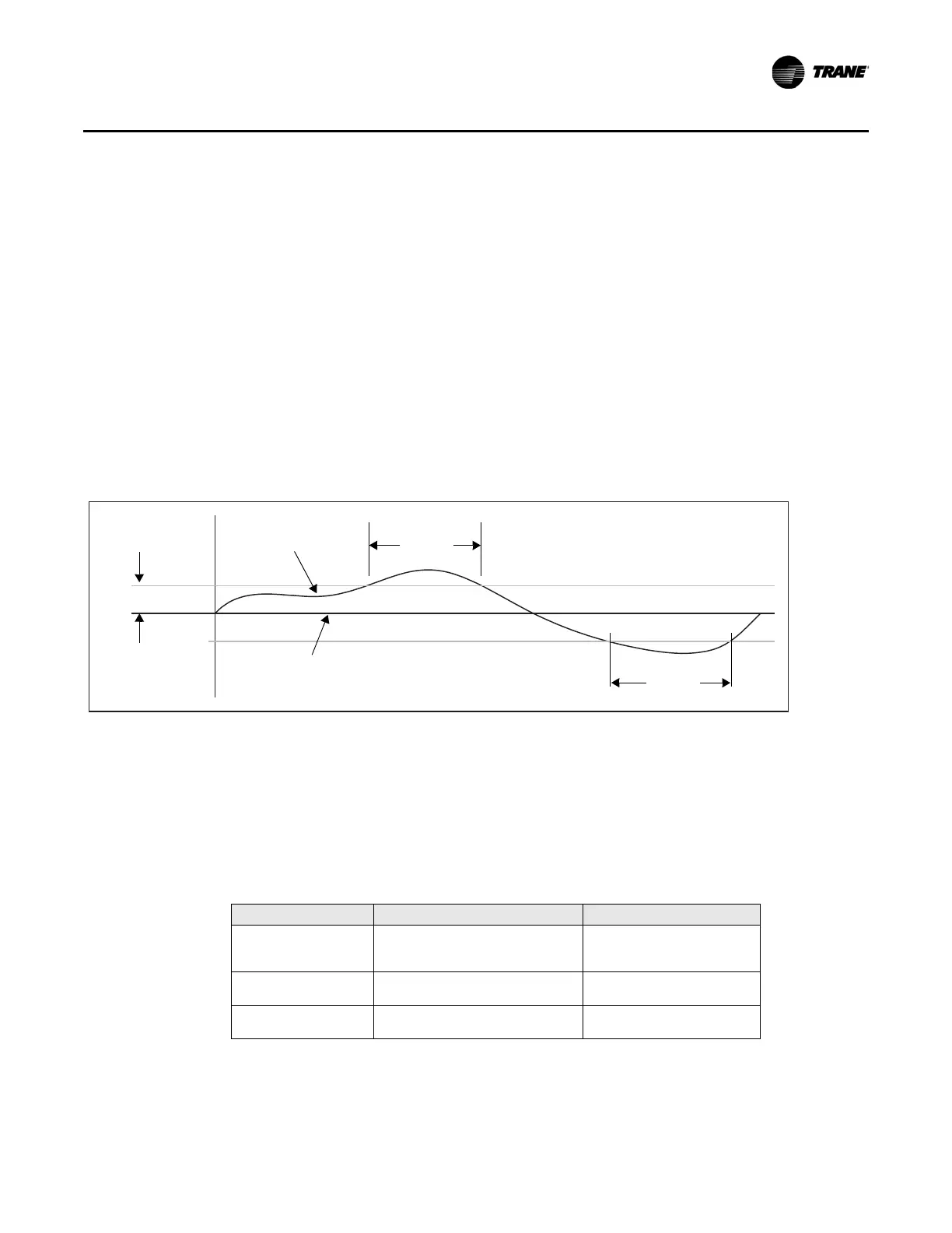
Figure 21, the error deadband is set at 2.0°F (1.1°C). As long as the absolute value of the error is
less than th
e 2.0°F (1.1°C), the PID output cannot change. If the absolute value of the error does
exceed 2.0°F (1.1°C), the PID output can change.
Figure 21. Error deadband
Control
Control
Setpoint
Process
variable
Error deadband
Error
As shown in Figure 21, the error deadband is a means of limiting how often an actuator is
controlled. If a PID loop controls a chilled water valve, this is not so important. But if a PID loop
controls how many stages of cooling are being used, it is important to limit equipment cycling.
Typical Applications
Table 10 shows reasonable deadbands for several applications. The error deadband can also be
calculated as described in the following sections.
Table 10. Error deadband settings for applications
Application Suggested Error Deadband Notes
Modulating output
(analog or floating
point binary)
0.5°F (0.3°C) for temperature
0.01 in. wc. (2.5 Pa) for duct static
pr
essure
De
pendent on resolution of
th
e process
variable sensor
Direct expansion (DX)
cooling
4.0°F (2.2°C) for temperature Staging application
Cooling towers—fan
staging
2.5°F (1.4°C) for tem
perature Staging application
Adjusting Error Deadband for Modulating Outputs
In most applications, start with an error deadband of five or ten times the sensor resolution. For
example, thermistors have a resolution of approximately 0.1°F (0.06°C), so a good error deadband

 Loading...


