RLC-SVU007E-GB
19
11UNT-PRC002-GB
Sound power levels
Discharge
Measurement conditions:
Measurements taken in a room adjacent to the room containing the FWD, at the outlet of the rectangular duct (1.5 m
long) fixed to its discharge opening.
Fan Power level in dB(A), per Hz frequency band Overall power
Unit speed 125 250 500 1000 2000 4000 8000 dB(A)
1 55 50 42 37 37 31 30 46
FWD 08 2 57 54 47 40 30 38 40 50
3 58 57 50 42 32 40 43 53
1 57 51 45 42 34 33 28 48
FWD 10 2 58 54 48 45 38 39 35 51
3 60 58 50 48 40 42 39 54
1 57 51 45 42 34 33 28 48
FWD 12 2 58 54 48 45 38 39 35 51
3 60 58 50 48 40 42 39 54
1 56 62 50 48 39 38 36 56
FWD 14 2 61 66 55 53 47 46 45 60
3 63 69 58 56 50 50 49 63
1 57 63 51 49 40 39 37 57
FWD 20 2 61 66 55 53 47 46 45 60
3 63 69 58 56 50 50 49 63
Intake
Measurement conditions:
Measurements taken at the horizontal air intake.
Fan Power level in dB(A), per Hz frequency band Overall power
Unit speed 125 250 500 1000 2000 4000 8000 dB(A)
1 56 55 55 53 46 45 42 57
FWD 08 2 63 62 60 60 53 53 53 64
3 66 65 63 62 56 55 57 67
1 62 58 55 58 51 48 44 61
FWD 10 2 66 63 60 62 56 55 52 66
3 70 67 63 65 59 59 57 69
1 62 58 55 58 51 48 44 61
FWD 12 2 66 63 60 62 56 55 52 66
3 70 67 63 65 59 59 57 69
1 66 65 65 65 57 50 46 68
FWD 14 2 73 72 69 71 64 59 57 74
3 78 76 73 75 69 64 63 78
1 68 72 64 64 56 52 50 69
FWD 20 2 76 76 68 71 65 61 61 75
3 78 79 71 74 69 66 66 78
Wiring and Port Descriptions for MODBUS, BACnet and LonTalk
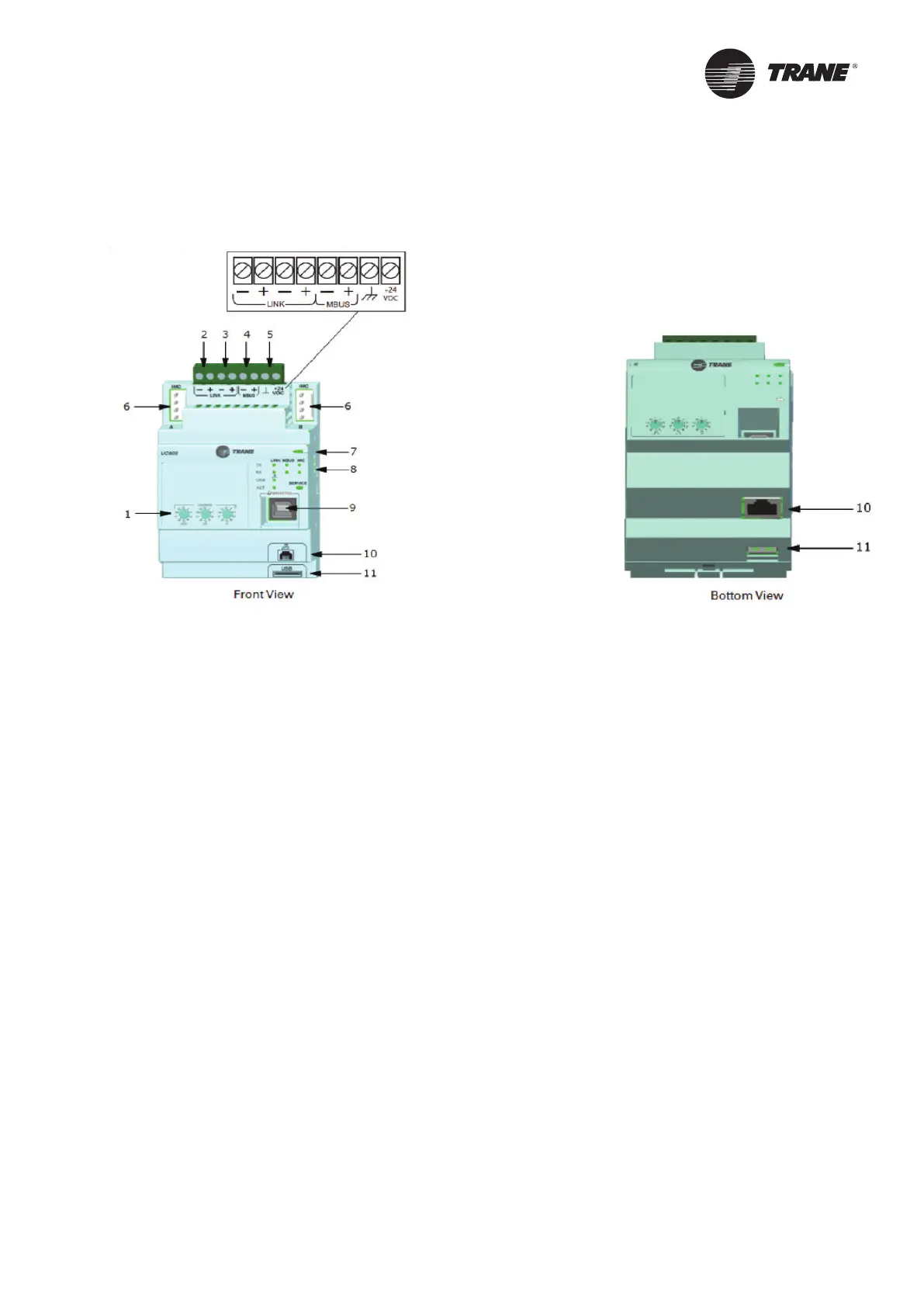
Figure 1 illustrates the UC800 controller ports, LEDs, rotary switches, and wiring terminals. The numbered list
following Figure 1 Wiring locations and connection ports corresponds to the numbered callouts in the illustration.
Figure 1 –
Wiring locations and connection ports of UC800 controller
1. Rotary Switches for setting BACnet
®
MAC address or MODBUS ID.
2. LINK for BACnet MS/TP, or MODBUS Slave (two terminals, ±). Field wired if used.
3. LINK for BACnet MS/TP, or MODBUS Slave (two terminals, ±). Field wired if used.
4. Machine bus for existing machine LLIDs (IPC3 Tracer bus 19.200 baud). IPC3 Bus: used for Comm4 using TCI or
LonTalk
®
using LCI-C.
5. Power (210 mA at 24 Vdc) and ground terminations (same bus as item 4). Factory wired.
6. Not used.
7. Marquee LED power and UC800 Status indicator.
8. Status LEDs for the BAS link, MBus link, and IMC link.
9. USB device type B connection for the service tool (Tracer TU).
10. The Ethernet connection can only be used with the Tracer AdaptiView display.
11. USB Host (not used).
Smart Com protocol
There are four connections on the UC800 that support the communication interfaces listed. Refer to Figure 2 for the
locations of each of these ports.
• BACnet MS/TP
• MODBUS Slave
• LonTalk using LCI-C (from the IPC3 bus)
Rotary Switches
There are three rotary switches on the front of the UC800 controller. Use these switches to define a three-digit
address when the UC800 is installed in a BACnet or MODBUS system (e.g., 107, 127, etc.).
Note:
Valid addresses are 001 to 127 for BACnet and 001 to 247 for MODBUS.

 Loading...


