82 CNT-SVX17G-EN
Troubleshooting
Translating Multiple Diagnostics
The controller senses and records each diagnostic independently of other diagnostics. It is possible
to have multiple diagnostics present simultaneously. The diagnostics are reported in the order they
occur. The reported alarm message is made up of two parts. The first part is the Trane alarm level.
The second part is the alarm message text. The level and the text are separated by one space. The
total length must be equal to or less than 30 characters. Table 51 through Table 55 describe alarm
leve
ls and repor
ted alarm message text.
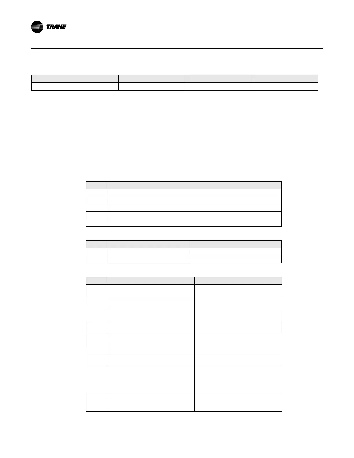
Table 51. Trane alarm levels
Level Description
P Normal; occurs immediately following a power-up reset
0 Normal
1 Informational message
2 Service required
3 Critical alarm
Table 52. Latching diagnostics, reset required
Level Reported alarm message text Description
2 Invalid unit configuration Cannot use current configuration
2 Controller failure Controller self test failure
Normal Normal Normal Normal
a.When a temperature sensor fails after being valid, the controller generates a diagnostic to indicate the sensor loss condition. Th
e controller
automatically clears the diagnostic once a valid sensor temperature value is present (non-latching diagnostic).
b.When the unit configuration is invalid, all outputs are de-energiz
ed (0 VDC) so that they return to their normal state.
c.If system mode is heat or auto with a warm or hot primary air temperature.
Table 50. Controller diagnostics (continued)
Diagnostic Air valve Fan Reheat
Table 53. Automatically resetting diagnostics
Level Reported alarm message text Description
2
Discharge air temperature failure
(ve
ntilation flow control with reheat)
No valid discharge air temperature
2
Discharge air temperature failure
(ve
ntilation flow control without reheat)
Discharge air temperature valid, then
not valid
2
Discharge air temperature failure (space
temper
ature control or flow tracking)
Discharge air temperature valid, then
not valid
2
Primary air temperature
failure
a, b
Primary air temperature valid, then not
valid
2 Local space setpoint failure
b
Local space setpoint input valid, then not
valid
2 Space temperature failure
a, b
Space temperature valid, then not valid
2 Flow sensor failure
Flow signal not valid. Sensor open or
shorte
d
2 Flow sensor calibration failure
Flow did not calibrate successfully
(The Kavlico® p
ressure sensor input voltage
has to be 0.25 +/-0.06 volts during calibration.
If it is outside this range, the diagnostic is
generated.)
1 Freeze protection active
Ventilation flow control unit opened the
wa
ter valve(s) due to low source
temperature

 Loading...


