16 CNT-SVX11A-EN
Installation & Wiring
Zone Sensor Features
Fan Switch (Optional)
The zone sensor fan switch provides
the controller with an occupied (and
occupied standby) fan request signal of
off or auto. If the fan control request is
communicated to the controller, the
controller ignores the hardwired fan
switch input and uses the communicat-
ed value. The zone sensor fan switch
signal can be enabled or disabled
through configuration in the ZN524
controller.
ON or CANCEL Buttons
Momentarily pressing the on button
during unoccupied mode places the
controller in occupied bypass mode for
120 minutes. You can adjust the number
of minutes in the unit controller config-
uration using Trane’s service tool,
Rover. The controller remains in occu-
pied standby mode until the override
timer expires or until the cancel button
is pressed.
Communication Jack
Use the RJ-11 communication jack as
the connection point from Rover to the
communication link (when the commu-
nication jack is wired to the communi-
cation link at the controller). By access-
ing the communication jack via Rover,
entrance to all controllers on the link
may be gained.
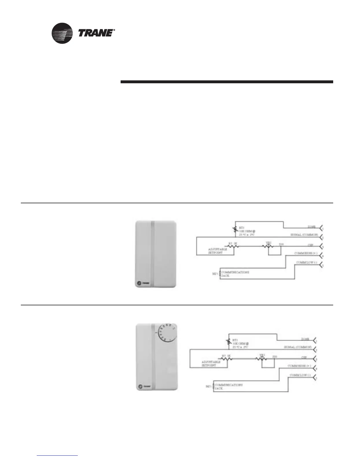
Table 6: Zone Sensor Options
Part number:
X13510628010
Description:
• Space temperature
(0.2 C resolution)
• Internal setpoint
• Communication jack
• Vertical case with Trane logo
Part number:
X13510606010
Description:
• Space temperature
(0.2 C resolution)
• External setpoint
• Communication jack
• Vertical case with Trane logo

 Loading...


