Mount the termination module
BMTK-SVN01D-EN 21
Installing electrical conduit
Use the conduit openings on the top of the Tracker termination module to
supply power or communication wires to the controller.
If the controller is mounted on a wall, you must use electrical conduit. If
the controller is mounted to a conduit box through which power, input/
output, and communications are supplied, you do not need to use
electrical conduit.
IMPORTANT
The 24 Vac wire conduit may not contain input/output or communica-
tion wires. Failure to comply will cause the Tracker controller to mal-
function due to electrical noise.
1. Remove one of the
7
/8 in. (22 mm) diameter plugs at the top of the ter-
mination module (Figure 13).
2. Install
1
/2 in. (12 mm) conduit connector (Figure 12 on page 19) in
opening.
3. Install the conduit jamb nut on the conduit connector threads and
tighten it to secure the connector to the Tracker panel.
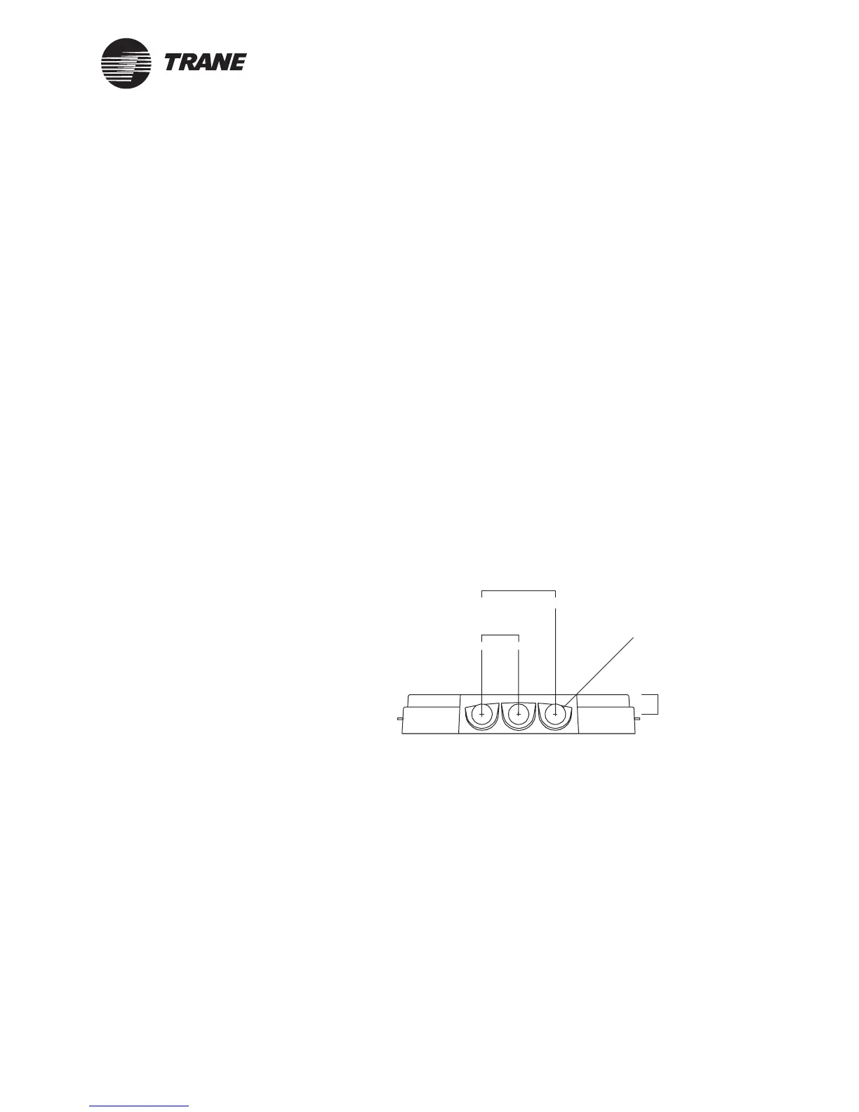
Figure 13. Electrical conduit installation
Termination module top view
0.75 in.
(2.02 cm)
ø 7/8 in.
(ø 22 mm)
1.5 in.
(3.81 cm)
3.0 in.
(7.62 cm)