XL 1050
18-HD80D1-6E-EN 9
5.3.2 Group 2 - Zoning Settings
Zoning settings are only available when a Zone Panel is connected and discovered.
Required Steps before enabling zoning:
1. Zone Panel must be powered (24VAC transformer)
2. Zone Panel must be connected to communicating bus (D, B)
3. All non-communicating zone temperature sensors must be connected to corresponding zone slots
4. All communicating zone temperature sensors must be addressed to corresponding zone number
5. All dampers should be installed and connected to corresponding zone slot
6. Discharge Temperature Sensor must be connected
7. Differential Static Pressure Sensor and probes should be installed and wired (only required for Auto Zone Sizing)
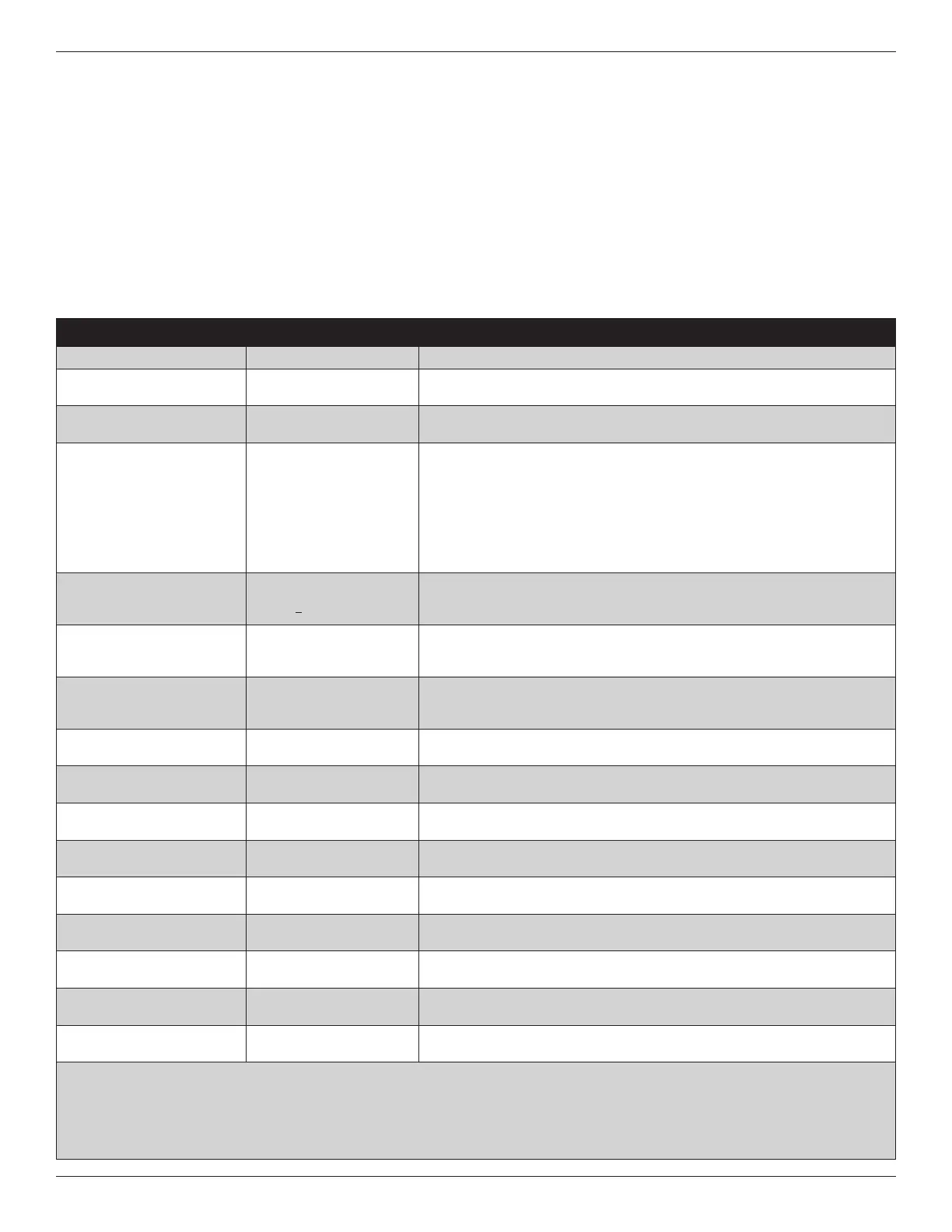
MENU ITEM OPTIONS [DEFAULT] DESCRIPTION
Zoning
Enable [Disable]
Select whether you want to enable zoning
Damper Travel Time
15 – [60] seconds
Select the damper travel time which matches the installed dampers. (All dampers
must have the same damper travel time)
Auto Detect Dampers
Manual, Auto
Manually select the number of zones or allow the 1050 Control to detect the number
of zones installed
Zone Airflow Capacity
Manual, Auto
Manually select the percentage of total system air flow each zone can handle (see
the table on the next page for manually sizing zones) or allow the 1050 Control to
calculate the percentage (Auto selection typically takes 10-12 minutes for up to 4
zones and 20-24 minutes for 5 zones or more)
Theres an additional setting if Auto Detection is selected. Zone Size Adjustment -
Normal, Less Aggressive, More Aggressive.
Less Aggressive setting results in slightly smaller zone sizes with reduced air flow while
More Aggressive setting results in slightly larger zone sizes with increased air flow.
% of total
5-100% for each zone, total
must be >100%
Manually input the zone sizes or edit the calculated zone sizes. The sum of the zone
sizes must be 100% or greater for zoning to proceed. See the Manual Zone Sizing
table on the following page..
Voting Zones
Select from assigned zones
Select which zones are Voting zones. Zones sized 25% or less are forced to non-voting
zones. Only voting zones are allowed to call for heating or cooling operation. Non-
Voting zones will receive capacity only when a voting zone is also requesting capacity.
Indoor Heating Airflow Offset
% (above and below cooling
airflow) ①
-50% – 50% [0%]
The air flow offset is the difference between the design cooling air flow (CFM per
ton x outdoor unit tonnage) versus the design heating air flow (max heating air flow
setting). The 1050 Control uses this offset to calculate and manage excess air.
Clamp LV for Auxiliary Heat ②
Disable, Enable
Select whether to clamp the system load value based on the sum of the calling
zones sizes to limit auxiliary heat operation.
Auxiliary Heat Threshold ②
25 – 99%
Select the threshold which allows auxiliary heat operation when the sum of the zone
sizes exceeds the selected threshold.
Discharge Temperature Limit
③ - Cooling
[Normal (38°F)], Extended
(34°F)
Select the minimum discharge temperature allowed during cooling operation
Discharge Temperature Limit ③
- Compressor Heating Only
[Normal (116°F)], Extended
(128°F)
Select the maximum discharge temperature allowed during compressor heating only
operation
Discharge Temperature Limit -
Compressor Heating w/Aux Heat ③
[Normal (160°F)], Extended
(170°F)
Select the maximum discharge temperature allowed during compressor heating with
auxiliary heating operation
Heating Fuel Type
[Gas], Oil
Select heating fuel type
Discharge Temperature Limit ③
- Gas Furnace Heating
[Normal (135°F)], Extended
(145°F)
Select the maximum discharge temperature allowed during indoor heat only
operation
Discharge Temperature Limit ③
- Oil Furnace Heating
[Normal (160°F)], Extended
(170°F)
Select the maximum discharge temperature allowed during indoor heat only
operation
Discharge Temperature Limit ③
- Hydronic Heating
[Normal (135°F)], Extended
(145°F)
Select the maximum discharge temperature allowed during indoor heat only
operation
③ This setting only applies to systems with an indoor unit type of Gas/Oil or Electric
② This setting is only available when the outdoor unit type is configured as VSPD
③ If the discharge temperature exceeds the max/min limits the following occurs: 1) Heating/cooling operation is defeated 2) Indoor blower is cycled
ON (VS blower runs at continuous fan speed) and 3) All supply dampers are driven full open
NOTE: Discharge Temperature Limit trips will create an alert (SOP.004.56) and heating/cooling operation is temporarily defeated. Once the discharge
temperature is below the max limit and the minimum off time has elapsed, zoning operation will resume and the alert will clear.
 Loading...


