Diagnostics and Troubleshooting
154 UNT-SVX07J-EN
6. After replacing modules, commission the unit by
performing at a minimum, “Fan Speed Response
Verification,” p. 79.
Application Notes
The ECM motor has some notable differences to
traditional designs.
RPM Mode
The motors are programmed from the factory to run in
rpm mode and will not change rpm based on external
static pressure, except at the performance limits of the
motor/controller. For ducted units, the units are shipped
with the rpm set for 0.2 inches ESP for High, Medium, and
Low speeds. The speeds can be manually changed for
high, medium, and low operation, but shall not be
changed for the electric heat actuation speeds.
Generally, the fans deliver less cfm for the same rpm, if the
static is increased and the power will decrease. The fan will
deliver more cfm for the same rpm, if the static is
decreased and the fan power will increase. A unit with high
static configuration should not be used to free-deliver air
(i.e., with no ducting attached).
Field Power Wiring
This motor uses an electronic variable speed motor
control, which includes a line reactor to minimize power
line harmonic currents. It is recommended that good
wiring practices be followed to manage building electrical
power system harmonic voltages and currents to avoid
electrical system problems or other equipment
interaction.
Performance Boundaries
While the speeds of the fan motors can be adjusted, never
program a fan speed higher than 1700 rpm, or lower than
450 rpm. In many cases, units configured for high-static
operation will not achieve the desired rpm if the ESP of the
unit is too low, or the unit is allowed to “free-discharge.”
The VelociTach motor control board contains settings that
will limit the output power of the motor under these
overload conditions. If the motors cannot achieve rpm
close to the target for a specific period of time, the unit will
disable electric heat and fan-status indicators.
MCA/MOP and Power Draw
ECM motors have variable output but are shipped at
specific settings to deliver proper performance and
reliability. The power draw indicated in the catalog
indicates the power consumed when applied properly (as
shipped and with the nominal ESP applied). However, the
nameplate of the unit indicates the maximum input draw
of the motor, as the motor settings can be changed to draw
more power.
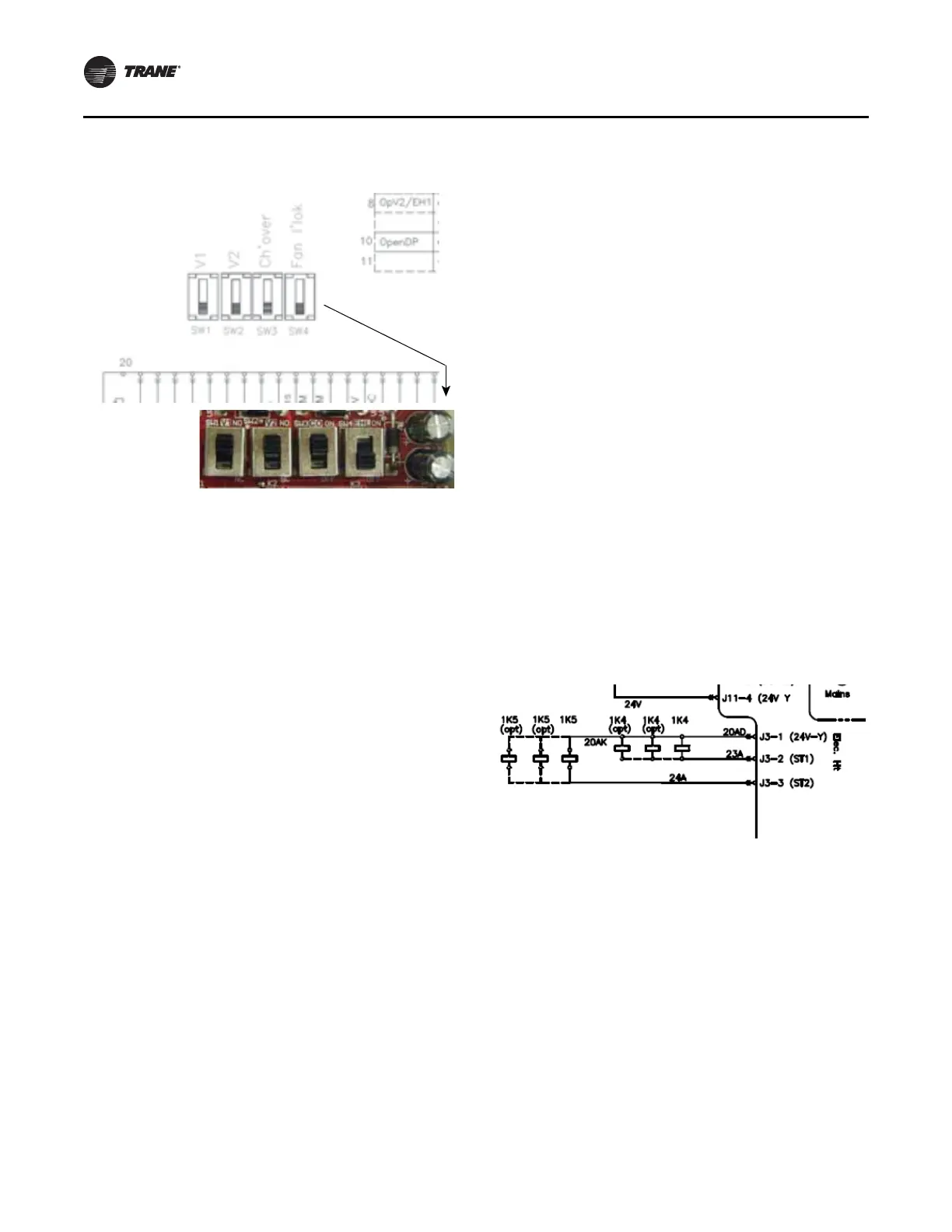
Electric Heat Relays
For quiet operation, units employ power relays instead of
definite purpose contactors for electric heat actuation. The
coils of multiple relays are hooked in parallel to simulate
a multi-pole contactor, as shown in Figure 115. In
Figure 115, two sets of three relays are used to perform the
function of a two 3-pole contactors.
Figure 114. Ensure CSTI adapter board switches are set
correctly
Figure 115. Sample arrangement: electric heat relay