Dimensions and Weights
20 UNT-SVX07J-EN
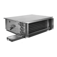
Model C Horizontal Concealed
Figure 7. Model C Horizontal concealed unit
Top Vi e w
2 5/16 in.
E
Back inlet duct collar
9/16 in.
9/16 in.
Optional
disconnect
switch
Aux
box
5 1/4 in.
15 1/2 in.
7/8 in. KO
control
wiring
1 5/8 in.
3 1/4 in.
2 in.
1 3/4 in.
1 3/4 in.
2 5/16 in.
3 1/4 in.
(4) 5/8 in. dia keyslot
hanger holes
Secondary drain connection
for 3/8 in. ID tube
Main drain connection
for 7/8 in. OD copper
tube and clamp
Control
box
(2) 5/8 in. bolt holes
3/4 in. 3/4 in.
Front View
RH Piping
6 15/16 in.
B
C
D
1 11/16 in. 1 11/16 in.
6 3/8 in.
Aux box
optional
6 1/4 in.
Control box
1 3/8 in.
2 7/8 in.
1 3/32 in. KO
7/8 in. KO
Power
wiring
bottom
only
A
2 7/16 in.
8 7/8 in.
5 5/16 in.
Front outlet
duct collar
Front View
LH Piping
1 1/8 in.
Aux box optional
Control box
Auxiliary
drain pan
Coil connections
26 3/4 in.
4 7/8 in. x F
Bottom inlet
open
10 1/16 in.
Filters
Air
flow
1 in. duct collar
27 3/16 in.
Back duct collar
5/8 in.
Filter door used with
back duct collar only
Back inlet duct collar
14 1/8 in.
6 1/8 in.
5/8 in.
1 in. duct collar
Side View
Inlet Options
Table 5. Model C Horizontal concealed unit dimensions (inches)
Unit Size 200-300 400 600 800 1000-1200
No. Fans1122 3
No.Motors 1 1 1 1 2
A 32 11/16 37 11/16 47 3/16 55 11/16 74 11/16
B 21 5/16 26 5/16 35 13/16 44 5/16 63 5/16
Notes: Coil connections are always on the drain pan side and opposite the control box. Coil connections are 5/8-in. O.D. sweat. See the Coil Connections
section for locations. All duct collar dimensions are to the outside of the collar. See the Fresh Air Openings Locations section for dimensions.
 Loading...


