ECM Overview and Setup
74 UNT-SVX07J-EN
• The motor control board can accept slightly over-
biased inputs up to 12 VDC, and the
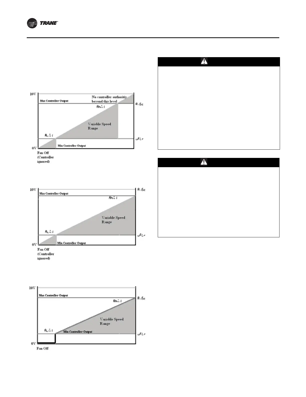
Aisc parameter
can be set to a value less than 1.0 to compensate.
VSP Setup Examples
Potentiometer/Rheostat For VSP
A courtesy 10 VDC supply is provided that can support a
10-mA draw. The use of a 1K or a 10K potentiometer is
recommended, and only a stand-alone potentiometer (not
shared with any other electrical system) should be
employed. When a simple potentiometer is used as
depicted in Figure 55, the
vflr setting will define a null-
zone (off).
The typical connection is depicted in Figure 55; however,
please consult the unit schematic for the most updated
instruction, as this is provided as reference only.
Figure 52. Example 1:
vflr set too high and Aisc set
too high
Figure 53. Example 2:
vflr set too high but Aisc set
correctly
Figure 54. Example 3:
vflr set correctly and Aisc set
correctly
WARNING
Hazardous Voltage w/Capacitors!
Failure to disconnect power and discharge capacitors
before servicing could result in death or serious injury.
Disconnect all electric power, including remote
disconnects and discharge all motor start/run
capacitors before servicing. Follow proper lockout/
tagout procedures to ensure the power cannot be
inadvertently energized. For variable frequency drives or
other energy storing components provided by Trane or
others, refer to the appropriate manufacturer’s literature
for allowable waiting periods for discharge of
capacitors. Verify with an appropriate voltmeter that all
capacitors have discharged.
For additional information regarding the safe discharge
of capacitors, see PROD-SVB06A-EN
WARNING
Safety Alert!
You MUST follow all recommendations below. Failure
to do so could result in death or serious injury. All
settings take effect immediately, including fan startup,
enabling of electric heat. Caution should be taken to
stay clear of hazardous voltages, moving parts and
electric heat elements while making adjustments to the
motor control board. If it is not practical to stay clear of
these areas during adjustment of the motor control
board, please contact Trane Global Parts for
configuration kit that allows easy powering of the
motor control board outside of the unit with a
9V battery.