Installation - Controls
UNT-SVX07J-EN 81
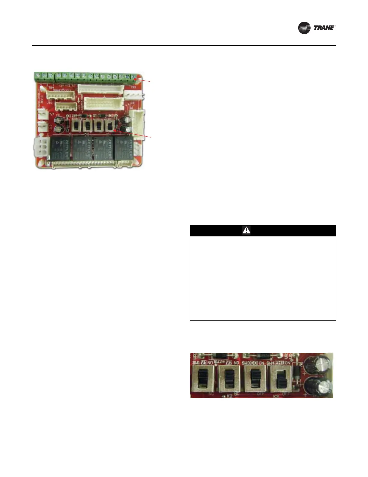
The CSTI adapter board provides all the hookups as the
standard adapter board, but in addition, provides hookups
for valve control (main and auxiliary coils), electric heat
control, and damper control. Screw terminal blocks
provide convenient access to fan controls and to end
device control. In addition, a courtesy 10 VDC supply is
provided for use with an external potentiometer or
rheostat. The 10 VDC supply supports up to 10 mA draw.
TB3 (right 13 positions) is normally used to provide:
• 24 Vac supply to a wall fan speed switch or
• 24 Vac supply to a field-installed unit-mounted
controller, or a wall-mounted controller or thermostat
• Inputs (returns) for thermostatic fan control: High,
Medium, and Low
• Inputs (returns) for cooling/heating requests
• Inputs (returns) for electric heat requests
• Inputs (returns) for damper operation requests
TB4 (left three positions) is normally used to control the
system with a 0–10 VDC input from a thermostat/controller
with a variable speed output, or a fan control rheostat.
The terminal block functional assignments and polarity
are shown for reference only, and the schematics that ship
with each unit should be consulted before wiring. Wiring
assignments are configured for each unit.
CSTI Adapter Board Configuration
For CSTI units, the board mounted switches have to be set
appropriately to enable the desired functionality.
Figure 59. CSTI adapter board and field connections
1. VSP 10V
2. VSP 0–10V
3. VSP DC COM
1. 24 Vac B (hot)
2. 24 Vac Y (gnd)
3. High
4. Medium
5. Low
6. V1Op/Cooling
7. V1Cl (not std)
8. Not used
9. Not used
10. V2Op/EH1St/Heating
11. V2Cl/EH2St (not std)
12. Damper Open
13. Dmp Cl (not std)
Customer low-voltage
interface for fan speeds,
variable fan speed, and
24 Vac supply, valve control,
EH control, damper control,
condensate overflow status
Valve(s), electric heat, and
changeover configuration
switches (factory-set)
3
2 1 13 12 11 10 9 8 7 6 5 4 3 2 1
CAUTION
Burn Hazard!
Failure to follow this instruction could result in the unit
overheating and becoming hot to the touch, which
could result in minor or moderate injury, and/or
equipment damage. If SW4 is turned off, the factory/
customer controller/thermostat will be able to actuate
the electric heat while hot water is available or if the
fans have failed. This switch should NOT be turned off if
the unit schematic indicates that it should be on, to
prevent overheating of the unit (due to simultaneous
electric heat and hydronic heat actuation, or failure of
the fan) and to use the preferred hydronic heating over
electric heat.
Figure 60. CSTI board-mounted switches