2
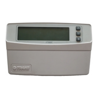
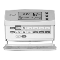
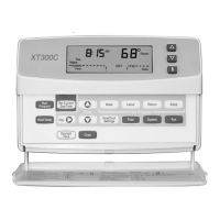
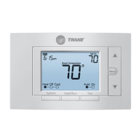
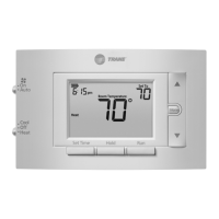
XT500C DELUXE PROGRAMMABLE HEAT-PUMP THERMOSTAT
69-1404
Pub. No. 18-HD25D2-2
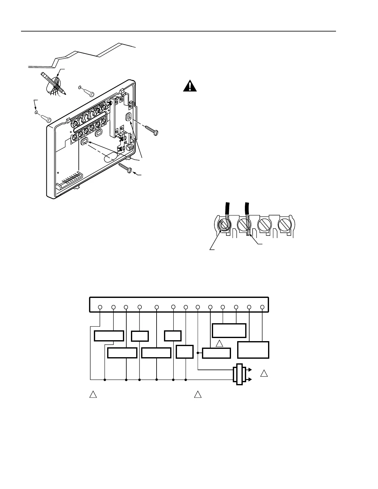
Fig. 2. Mounting the wallplate.
2. Use a pencil to mark the mounting holes. See Fig. 2.
3. Remove the wallplate from the wall and drill two 3/16
inch holes in the wall (if drywall) as marked. For firmer
material such as plaster, drill two 7/32 inch holes.
Gently tap anchors (provided) into the drilled holes until
flush with the wall.
4. Position the wallplate over the holes, pulling wires
through the wiring opening.
5. Loosely insert the mounting screws into the holes.
6. Tighten mounting screws.
WIRES
THROUGH WALL
WALL
MOUNTING
HOLES
M15044
MOUNTING
SCREWS
WALL
ANCHORS
(2)
M4826
FOR WRAPAROUND
INSERTION STRIP
7/16 IN. (11 MM).
FOR STRAIGHT
INSERTION STRIP
5/16 IN. (8 MM).
WIRING
All wiring must comply with local electrical codes and
ordinances. Refer to Fig. 3 for typical hookup diagram. A letter
code is located near each terminal for identification.
WARNING
Electrical Shock or Equipment Damage Hazard.
Can shock individuals or cause equipment
damage.
Disconnect power before wiring to prevent electrical
shock or equipment damage.
1. Loosen the terminal screws on the wallplate and
connect the system wires. See Fig. 4.
NOTE: Use 18 gauge, color-coded thermostat cable for
proper wiring.
2. Securely tighten each terminal screw.
3. Push excess wire back into the hole.
4. Plug the hole with nonflammable insulation to
prevent drafts from affecting the thermostat.
Fig. 3. Typical hookup of XT500C in a heat pump system.
COMPRESSOR
CONTACTOR 2
M17108
W
L1
L2
FAN
SWITCHOVER
VALVE
HUMIDISTAT
OPENS ON RISE
TAYSTAT253A
YY2
X2
THERMOSTAT
B RO
COMPRESSOR
CONTACTOR 1
EM. HT.
RELAY
TRANSFORMER
OT OT
OUTDOOR
TEMPERATURE
SENSOR
TAYSENS100A
G
HHF
DEFROST
CONTROLLER
1
2
POWER SUPPLY. PROVIDE DISCONNECT MEANS
AND OVERLOAD PROTECTION AS REQUIRED.
2
FEATURE NOT AVAILABLE
ON ALL SYSTEMS.
1
AUX.
HEAT
RELAY
BLUE
YELLOW
BROWN
GREEN
ORANGE
BLACK
WHITE
RED
Fig. 4. Proper wiring technique.