19RT-SVX31A-EN
Horizontal Discharge Conversion
YSC072 - 120
Supplies Needed by Installer for Conversion: 3 oz. tube of
high Temperature RTV sealant. ( 500°F / 260°C : Similar to
Dow Corning 736 )
Note: Failure to use recommended sealant could result in unit
performance loss.
If a unit is to be converted to a Horizontal discharge, the fol-
lowing conversion must be performed:
1. Remove RETURN and SUPPLY duct covers.
2. Place SUPPLY DUCT COVER over down-flow return
opening. (Insulation side down)
3. Using self-drilling screws, (or screws removed from duct
cover), screw through dimples to attach duct cover to base.
Supply Duct Cover
Screw into 4
dimples on top
edge
4. On original RETURN DUCT COVER, apply ¼” (6mm.)
continuous bead of 500°F RTV sealant around flange (op-
posite insulation side), as shown.
RTV Sealant
5. Slide RETURN DUCT COVER (insulation side up) into
supply opening until inward edge of duct cover engages
with the 2 retaining clips on the duct flange. Secure outward
edge of the duct cover with two screws.
Note: If Unit is equipped with Return Air Smoke Detector, refer
to field conversion instructions for horizontal discharge before
installing return air duct.
Note: The following units require a limit switch change
out. The additional limit switch is shipped attached to
the blower housing for these models. Proceed to Step
5 for the following models "ONLY". YSC060A**H,
YSC072A**H, YSC090A**H, YSC102A**H,
YSC120A**H.
5. After completing installation of the duct covers for hori-
zontal discharge, proceed to TCO-1 instructions.
TCO1 Instructions:
If the unit being installed is listed in the following table the
limit control TCO1 must be replaced with the extra limit con-
trol shipped in the heater compartment. Replace TCO1 fol-
lowing the instructions in steps 1through 4 below. If the unit
being installed does not correspond to any in the following
table, skip steps1 through 4 and go on to next step in the in-
stallation process.
Y*C036A**H, Y*C048A**H, Y*C060A**H, YHC060A**M
Y*C072A**H, YSC090A**M, Y*C092A**M, YHC092A**H,
Y*C102A**M, Y*C102A**H, Y*C120A**M, Y*C120A**H.
Unit Model Number
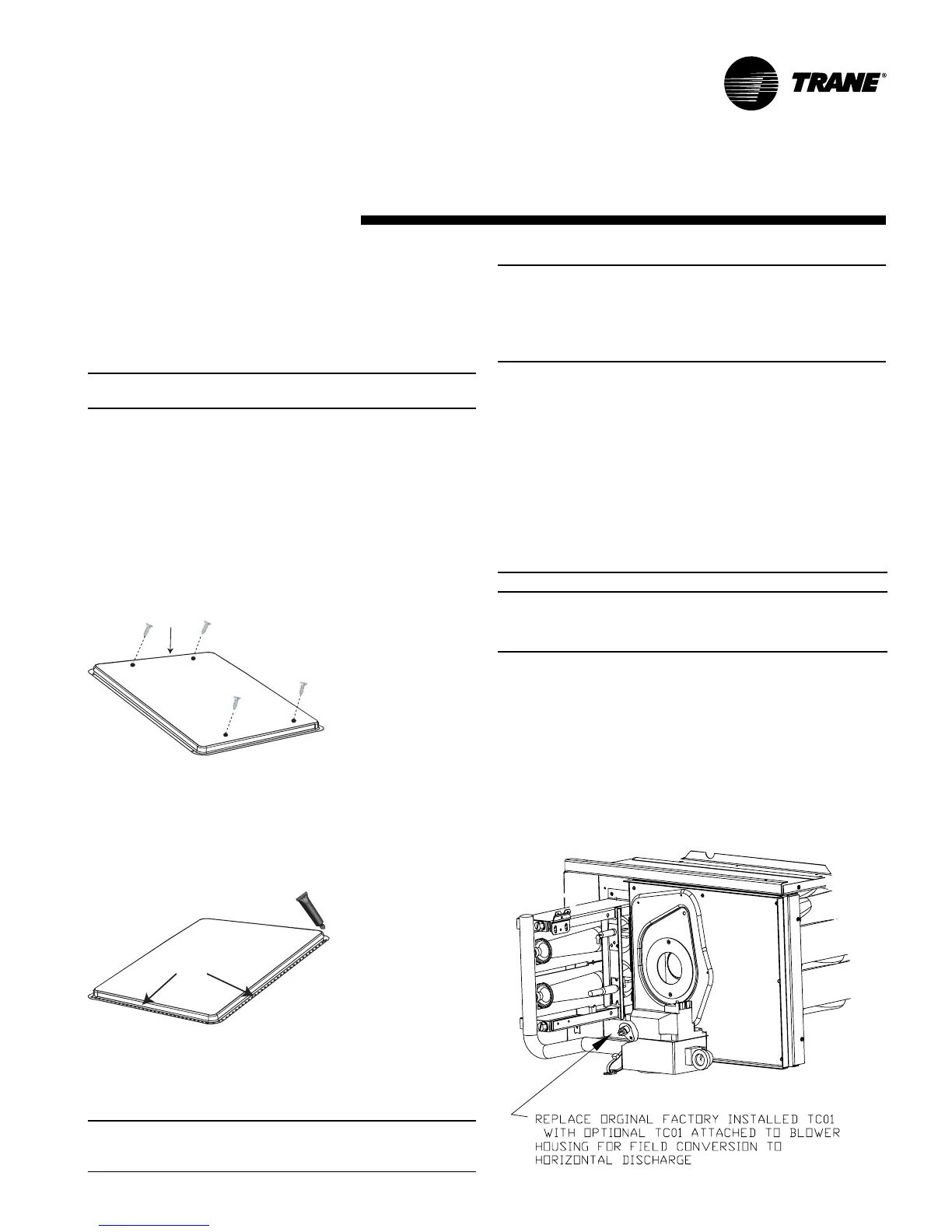
1. Remove the heat section access panel.
2. Remove TC01 from shipping location, attached to the
combustion blower.
3. Replace and discard the existing TC01 originally installed
at the factory for downflow operation with the TC01
shipped attached to the combustion blower for horizontal
operation.
4. Replace heat section access panel.
Installation