RT-SVX31A-EN16
The checklist listed below is a summary
of the steps required to successfully in-
stall a commercial unit. This checklist is
intended to acquaint the installing per-
sonnel with what is required in the in-
stallation process. It does not replace
the detailed instructions called out in
the applicable sections of this manual.
[ ] Check the unit for shipping damage
and material shortage; file a freight
claim and notify appropriate sales
representative.
[ ] Verfiy correct model, options and
voltage from unit nameplate.
[ ] Verify that the installation location of
the unit will provide the required
clearance for proper operation.
[ ] Assemble and install the roof curb (if
applicable). Refer to the latest edi-
tion of the curb installers guide that
ships with each curb kit.
[ ] Fabricate and install ductwork; se-
cure ductwork to curb.
[ ] Install pitch pocket for power supply
through building roof. (If applicable)
[ ] Rigging the unit.
[ ] Set the unit onto the curb; check for
levelness.
[ ] Ensure unit-to-curb seal is tight and
without buckles or cracks.
[ ] Install and connect a condensate
drain line to the evaporator drain
connection.
Factory Installed Economizer
[ ] Ensure the economizer has been
pulled out into the operating position.
Refer to the economizer installers
guide for proper position and setup.
[ ] Install all access panels.
Rigging
A Rigging illustration and Center-of-
Gravity dimensional data table is shown
in Figure 3. Refer to the typical unit op-
erating weights table before proceed-
ing.
1. The wooden top is secured to the
unit by a plastic strap. The plastic
strap is secured to the right front cor-
ner post of the unit with one screw.
Remove this screw to release the
strap. Remove the wooden top and
plastic strap. Replace the screw in
the right front corner post.
2. Remove protective covering from
around the unit.
DO NOT USE CABLES (CHAINS OR
SLINGS) EXCEPT AS SHOWN. OTHER
LIFTING ARRANGEMENTS MAY CAUSE
EQUIPMENT DAMAGE OR SERIOUS
PERSONAL INJURY.
EACH OF THE CABLES (CHAINS OR
SLINGS) USED TO LIFT UNIT MUST BE
CAPABLE OF SUPPORTING THE ENTIRE
WEIGHT OF THE UNIT.
LIFTING CHAINS (CABLES OR SLINGS)
MAY NOT BE THE SAME LENGTH. AD-
JUST AS NECESSARY FOR EVEN LEVEL
LIFT.
3. Rig the unit as shown in Figure 3. At-
tach adequate strength lifting slings
to all four lifting brackets in the unit
base rail. Do not use cables, chains,
or slings except as shown.
4. Install a lifting bar, as shown in Fig-
ure 3, to protect the unit and to facili-
tate a uniform lift. The minimum
disbetween the lifting hook and the
top of the unit should be 7 feet
(21m).
5. Test-lift the unit to ensure it is prop-
erly rigged and balanced, make any
necessary rigging adjustments.
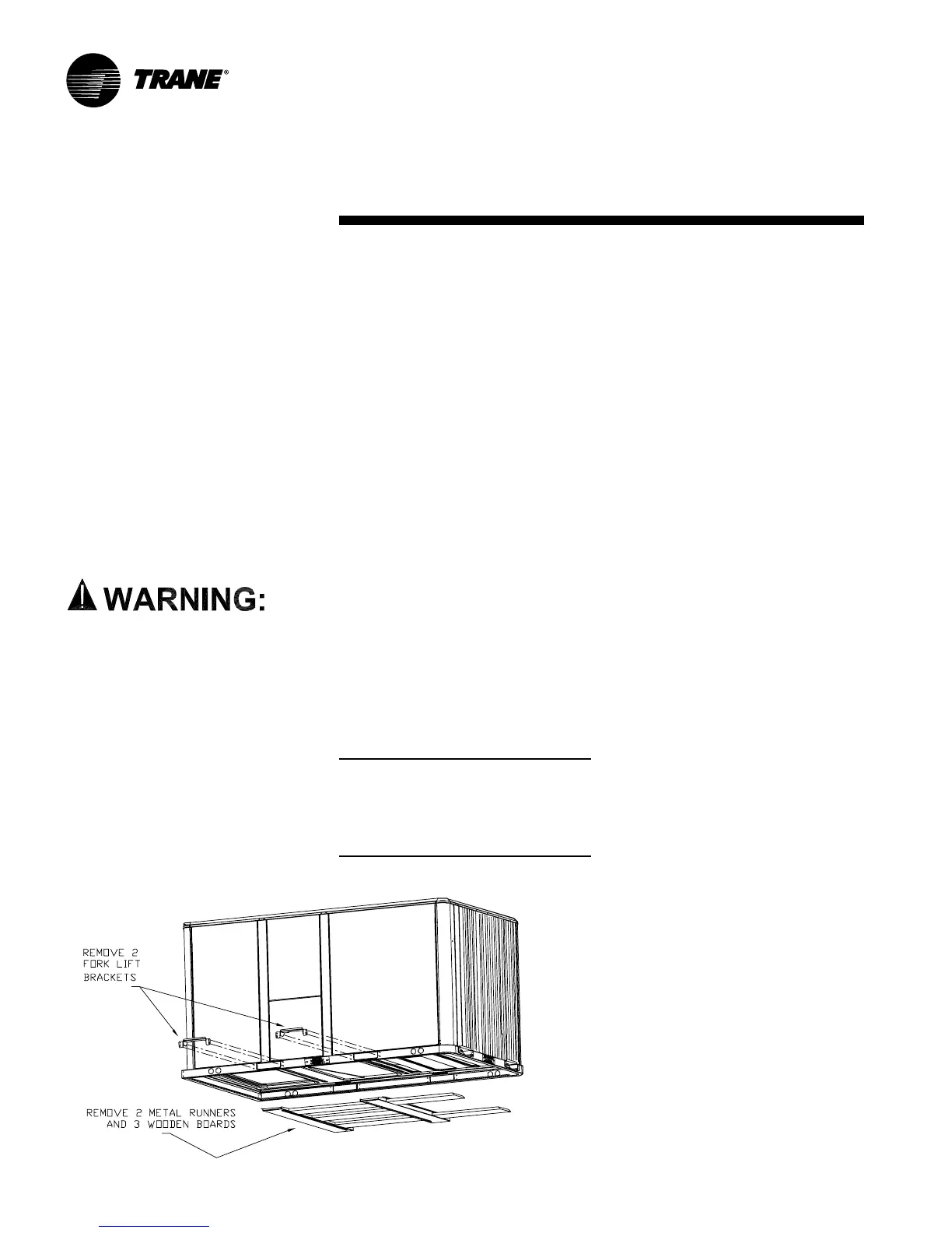
6. Lift the unit enough to allow the re-
moval of two Fork Lift brackets and
hardware. Remove the two Fork Lift
brackets, two metal runners and
three wooden boards as shown.
7. Downflow units; align the base rail of
the unit with the curb rail while lower-
ing the unit onto the curb. Make sure
that the gasket on the curb is not
damaged while positioning the unit.
General Unit Requirements
Note:
Before installation check that local
distribution conditions, nature of gas
and pressure. and the current state
adjustment of the appliance are
compatible.
Installation