Installation
RT-SVX38B-EN 17
Foundation
Horizontal Units
If the unit is installed at ground level, elevate it above the
snow line. Provide concrete footings at each support
location with a “full perimeter” support structure or a slab
foundation for support. Refer to Table 1, p. 17 for the unit’s
operating and point loading weights when constructing a
footing foundation.
If anchoring is required, anchor the unit to the slab using
hold down bolts or isolators. Isolators should be installed
to minimize the transmission of vibrations into the
building.
Table 1. Maximum unit & corner weights (lbs/kgs) and center of gravity dimensions (in/mm) - gas/electric models
Unit
Maximum Model
Weights
(a)
Corner Weights
(b)
Center of Gravity (in./
mm)
Tons Model No. Shipping Net A B C D Length Width
5 YSC060E 689/312 584/264 181/82 144/65 122/55 137/62 40/1025 24/600
6 YSC072E 975/443 843/383 296/134 209/95 158/72 180/82 39/980 21/542
7½ YSC090E 1016/461 884/401 346/157 198/90 159/72 181/82 36/909 20/519
8½ YSC102E 1125/510 987/447 325/147 278/126 174/79 210/95 41/1031 21/526
10 YSC120E 1149/522 1011/459 344/156 265/120 193/88 209/95 40/1020 21/538
(a) Weights are approximate.
(b) Corner weights are given for information only.
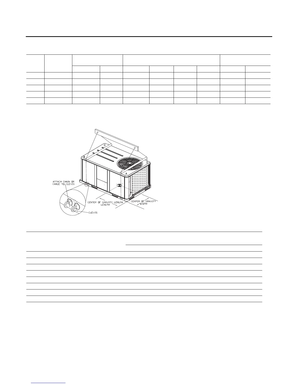
Figure 12. Rigging and center of gravity
Table 2. Factory installed options (fiops)/accessory net weights (lbs)
(a),(b)
YSC060ED YSC072E-120ED
Net Weight Net Weight
Accessory 5 Ton 6-10 Ton
Barometric Relief 7/3 10/5
Coil Guards 12/5 20/9
Economizer 26/12 36/16
Hinged Doors 10/5 12/5
Manual Outside Air Damper 16/7 26/12
Motorized Outside Air Damper 20/9 30/14
Oversized Motor – 8/4
Roof Curb 61/28 78/35
(a)Weights for options not listed are <5 lbs.
(b)Net weight should be added to unit weight when ordering factory-installed accessories.