EasyManua.ls Logo

Trane ZSASSMAL012 User Manual

Trane ZSASSMAL012
20 pages
To Next Page IconTo Next Page
Page #1 background imageLoading...
Page #1 background image
18-HH08D10-2
Model:
ZSASSMAL012
ZONING ASSEMBLY
IMPORTANT -- T
his Document contains wiring and service information. This is customer property and is to remain with this unit.
Please return to service information upon completion of work.
INSTALLER'S
GUIDE
ALL phases of this installation must comply with
NATIONAL, STATE AND LOCAL CODES
(1) Enclosure.
(1) System Controller.
(1) ZZEXPDAL010 Expander Board (up to four
zones per board). A second Expander Board may be
added for eight zones
(3) ZZCARDAL010 Zone/Bypass Control Cards one
for each zone plus one for modulated bypass (if
desired).
(1) Discharge Air Temperature Sensor (DAT).
Note: If modulated bypass is utilized, one zone slot is
used up, leaving room for three zones, with one
Expander Board or seven zones with two Ex-
pander Boards.
IMPORTANT: The System Controller must be connected
to a compatible communicating Comfort Sensor for proper
operation. The Comfort Sensor senses indoor conditions
and customer commands and transmits this information to
the System Controller. All system electrical control func-
tions are provided by the System Controller.
GENERAL
These instructions do not cover all variations in systems
nor provide for every possible contingency to be met in
connection with installation.
This Installer's Guide covers multiple zone applications of
the ZSASSMAL012 Zoning Assembly. Systems covered,
include single or variable speed indoor units, (furnaces or
air handlers) matched with single speed, two speed or two
compressor outdoor units (straight cooling or heat pump).
Two separate straight cooling outdoor units or a packaged
unit may also be controlled.
Dual fuel (add on) heat pumps are included in the above
heat pump categories. Single stage and two stage dual fuel
heat pumps do not require the Plus-One kit.
The Zoning Assembly includes the following components
for two zone application with modulated bypass or a three
zone application without bypass:
(3) ZONE/BYPASS
CONTROL CARDS
EXPANDER BOARD
SYSTEM CONTROLLER
© 2008 Trane
Question and Answer IconNeed help?

Do you have a question about the Trane ZSASSMAL012 and is the answer not in the manual?

Trane ZSASSMAL012 Specifications

General IconGeneral
BrandTrane
ModelZSASSMAL012
CategoryThermostat
LanguageEnglish

Summary

General System Information

System Overview and Component List

Covers system variations, lists Zoning Assembly components.

Inspection and Initial Setup

Shipping Damage and Parts Check

Procedure for checking shipping damage and reporting missing parts.

System Controller Placement and Mounting

Guidelines for locating, marking, and drilling for the System Controller.

Expander Board and Control Card Installation

Instructions for connecting Expander Boards and Control Cards.

Electrical Shock Hazard Warning

Critical safety warning regarding power disconnection before installation.

Wiring Practices and System Controller Terminals

Guidelines for wiring, including proximity to inductive loads and terminal blocks.

Wiring and Configuration

Control Wiring Routing and Connections

Instructions for routing wiring and connecting to terminal blocks.

Zone Sensor and Damper Motor Wiring

Details on wiring zone sensors and damper motors.

System and Expander Board Switch Configuration

Guidance on setting system and expander board dip switches for operation.

Communicating vs. Analog Sensor Setup

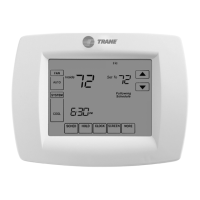
Explains differences and connection requirements for digital and analog sensors.

Master Scheduler Integration with Sensors

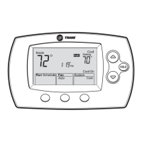
Details on using the Master Scheduler with various sensor types.

Component Installation and Checks

Optimal Comfort Sensor Placement

Recommendations for locating comfort sensors for accurate air control.

Damper Wiring and Transformer Sizing

Guidance on installing multiple dampers and sizing 24V transformers.

System Operation Verification

Steps for verifying zone addresses and system operation status.

Discharge Air Sensor Operation

How the sensor monitors supply air temperature and affects system shutdown.

Discharge Air Sensor Settings and Specs

Information on sensor settings, specifications, and operating ranges.

Discharge Air Sensor Installation

Sensor Mounting and Duct Hole Preparation

Instructions for cutting duct holes and mounting the sensor.

Sensor Positioning for Accurate Readings

Guidelines for positioning the sensor relative to heat sources and airflow.

Ductwork and System Settings

Wiring Connections Inside a 4" Box

Steps for making wiring connections within a 4" electrical box.

Discharge Air Sensor Wiring to Controller

Details on wiring the discharge air sensor to the system controller.

Sensor Checkout Procedure

Method for checking the functionality of the discharge air sensor.

Zone Card Settings for Ductwork Dampers

Table and guidance for setting zone control card dip switches for dampers.

Zone Card Damper Settings Table

Airflow Velocity and Damper Weight Chart

Table correlating airflow, damper size, and weight for zone control.

Figure 7: Single Speed Outdoor Unit Wiring

Wiring Notes and System Configuration

Important notes, load shed, humidistat, and system configuration settings.

Normal Operation and Zoning Settings

Dip switch settings for normal operation and zoning configurations.

Test Mode Operation for Single Speed Systems

Procedures for operating the system in test modes.

Figure 8: Variable Speed Indoor Unit Wiring

System Type Configuration and Notes

Notes on system types (two-step, two-compressor) and general wiring notes.

Operation and Zoning Switch Settings

Configuration for normal operation, zoning, and test modes.

Figure 9: Dual Fuel Heat Pump Wiring

Dual Fuel Heat Pump System Notes

Notes for dual fuel heat pump configurations and wiring.

Operation, Zoning, and Test Mode Settings

Settings for normal operation, zoning, and test modes for dual fuel systems.

Figure 10: Two Single Speed Heat Pump Outdoor Units Wiring

Air Handler and Outdoor Unit Wiring Notes

Notes on air handler connections and outdoor unit wiring for dual heat pumps.

System Operation and Configuration Settings

Configuration for normal operation, zoning, and test modes.

Figure 11: Single Speed Cooling Outdoor Unit Wiring

Indoor Unit and Cooling Outdoor Unit Notes

Notes for single speed cooling outdoor units with hydronic coils.

System Operation and Zoning Configuration

Settings for normal operation, zoning, and test modes.

Comfort Sensor Connection Diagram

Connecting Communicating and Analog Sensors

Diagram and notes for connecting various comfort sensors to the system controller.

Zone/Bypass Control Card Switch Settings

Setting Damper CFM Percentages

Guide to setting dip switches for zone damper CFM control and bypass.

Zone/Bypass Control Card Connection Diagram

Thermostat, Controller, and Expander Board Wiring

Wiring diagram for connecting thermostats, controller, and expander boards.

Damper Power Supply and System Notes

Notes on damper power requirements and system integration.

Zone Expander Board and System Configuration

System and Zoning Switch Configuration

Details on setting switches for system type, zoning, and test modes.

Expander Board and Zone Card Settings

Instructions for configuring expander boards and zone/bypass control cards.

Figure 16: 16i Packaged Unit Wiring

Packaged Unit System Notes and Configuration

Notes and configuration for 16i packaged units with two-step scroll.

Operation, Zoning, and Test Mode Settings

Settings for normal operation, zoning, and test modes for packaged units.

4DCZ6 Packaged Unit Wiring Diagram

Unit Warnings, Models, and Voltage Notes

Safety warnings, model information, and voltage considerations for the unit.

Low Voltage Wiring and Component Connections

Detailed low voltage wiring diagram and component connections.

4WCZ6 Packaged Unit Wiring Diagram

Unit Safety, Model, and Voltage Information

Safety precautions, model identification, and voltage details for the unit.

Low Voltage Wiring and Component Layout

Wiring schematic and component connections for low voltage circuits.

4YCZ6 Packaged Unit Wiring Diagram

Unit Warnings, Models, and Voltage Requirements

Safety warnings, model numbers, and voltage requirements for the unit.

Low Voltage Wiring Schematics and Connections

Detailed wiring diagram of low voltage circuits and component hookups.

Related product manuals