APPENDIX B: SERIAL PORT INFORMATION
B.1 SERIAL PORT MODES
B.1.1 FULL DUPLEX MODE
The Full Duplex Mode provides a Demand serial transmission mode and is selected by
setting A3 to “d” and A6 to “0”. The Demand mode allows control from a host device, usually
a PC. Figure B-1 shows a suggested cable diagram for interface to a PC. Figure B-2 shows
the serial data format for the Demand Mode.
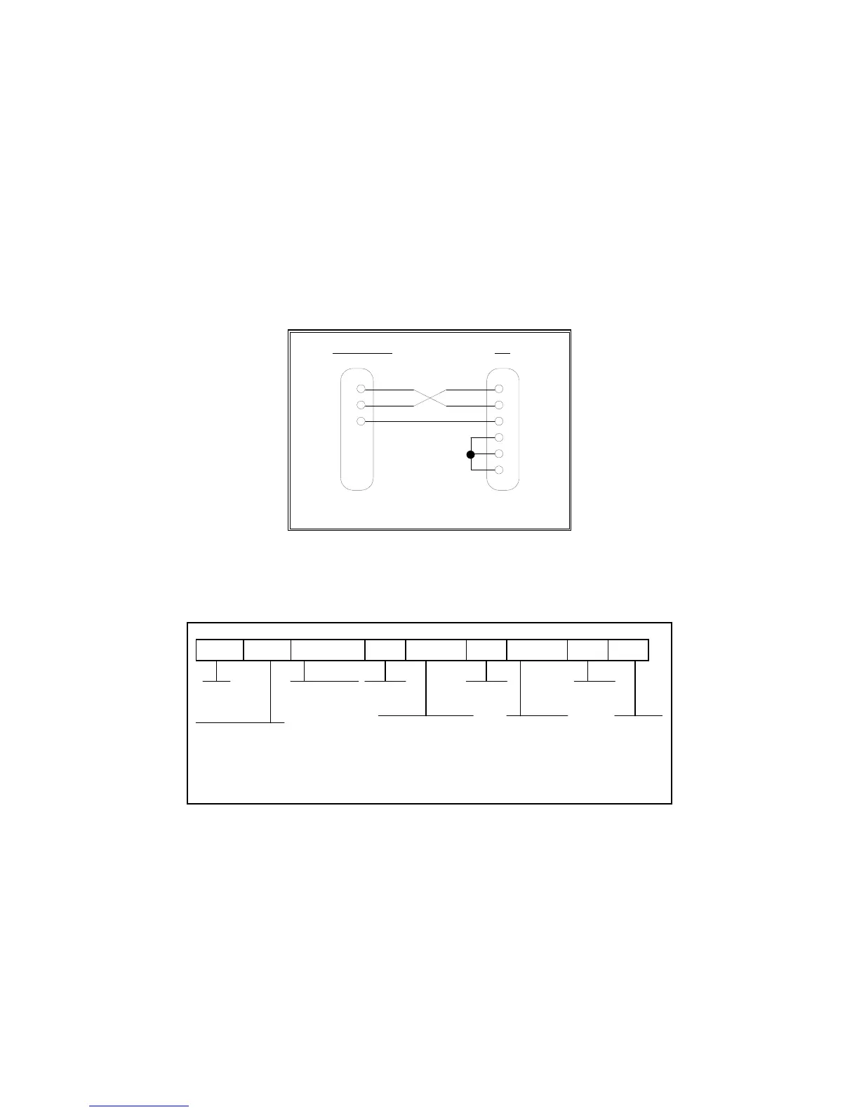
INDICATOR PC
2 RXDRXD 2
TXD 3
S. GND 5
3 TXD
5 S. GND
6 DSR
4 DTR
8 CTS
DSUB9 DSUB9
FIGURE B-1. Cable Diagram for Indicator to IBM PC
<STX> <POL> xxxxx.xx <LB/KG> <GR/NT> <CR> <LF>
Polarity:
<SP> = Positive
"–" = Negative
Weight Data
Units:
lb = pound
kg = kilogram
Gross/Net:
GR = Gross
NT = Net
Start
Transmission
Carriage
Return
Line
Feed
<SP> <SP>
SpaceSpace
pc = pieces
cu = cusotm unit
pcs = pieces*
* Available on TI-500E and TI-500E-SS only
FIGURE B-2. Consolidated Controls Demand Mode
Page B-1
 Loading...