CHAPTER 2: INSTALLATION
2.1 STAINLESS STEEL ENCLOSURE
For indicators contained in a stainless steel enclosure, the rear cover must first be removed to
make the appropriate connections to the weigh platform, printer, remote display and power supply.
o remove the rear cover, simply remove the screws that secure it to the enclosure and set aside. T
NOTE: On earlier units, the rear cover must remain off to access the Setup Menu and calibration
procedures.
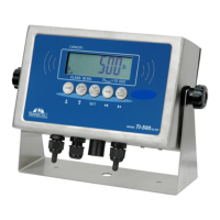
J8
S- SHE+ S+ E-
CPU
EPROM
J3
TXD RXD GND
J1
P+ P-
JP2
J4
J6
+5
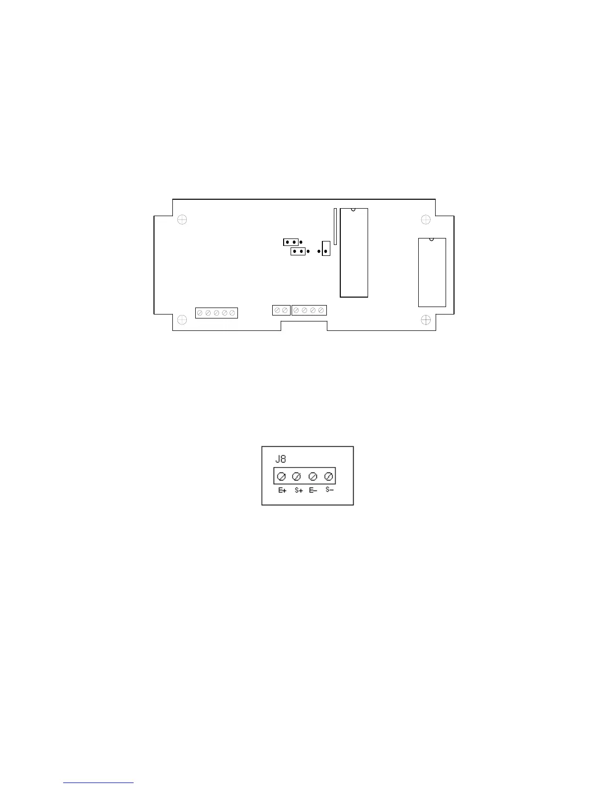
Figure 2-1: Neptune 4500 Main Circuit Board Overview
2.1.1 CONNECTING THE WEIGH PLATFORM
1. Connect your shielded load cell cable (not included) to the appropriate terminal on the
main board. Connection assignments for the Load Cell Terminals are shown in Figure
2-6.
Figure 2-2: Connection assignments for the Load Cell Terminal
Neptune 4500 Page 2-1