iii
Ne
tune 4500
LIST OF FIGURES
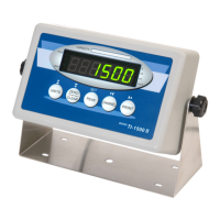
1-1 Neptune 4500 Front Panel...................................................................................................... 1-2
2-1 Neptune 4500 Main Circuit Board Overview .......................................................................... 2-1
2-2 Connection assignments for load cell..................................................................................... 2-1
2-3 Connection assignments for the serial communication terminal ............................................ 2-2
3-1 Setup Menu Key Assignments................................................................................................ 3-2
3-2 Setup Menu Chart................................................................................................................... 3-3
3-3 User Menu Key Assignments.................................................................................................. 3-4
3-4 User Menu Chart..................................................................................................................... 3-5
5-1 User Menu Key Assignments.................................................................................................. 5-3
6-1 Setup Menu Key Assignments................................................................................................ 6-2
7-1 Neptune 4500 Series LED Display Detail............................................................................... 7-1
7-2 Function Keys Layout ............................................................................................................. 7-2
B-1 Cable Diagram for Indicator to IBM PC .................................................................................. B-1
B-2 Consolidated Controls Demand Mode.................................................................................... B-1
B-3 Print Ticket .............................................................................................................................. B-2
B-4 Cable Diagram for Indicator to Printer .................................................................................... B-2
B-5 Consolidated Controls Continuous Mode ............................................................................... B-3
LIST OF TABLES
1-1 Neptune 4500 Series Product Matrix...................................................................................... 1-1
4-1 Invalid Setup Selections for commercial applications............................................................. 4-3
6-1 Calibration Value Table........................................................................................................... 6-3
7-1 Neptune 4500 Series Annunciator Definitions........................................................................ 7-2
C-1 Minimum Recommended Span Gain Table............................................................................ C-2
 Loading...