3
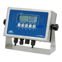
CONNECTING THE WEIGH PLATFORM
The
TI
-500
ships with a 15 ft shielded load cell
cable for connection to weigh platform’s load cell(s) or
junction box.
1.
Plug the cable’s 14-
pin
parallel interface
connector into the load cell port on the rear
panel of the indicator.
2.
Wire the bare wires and shield to the weigh platform’s load cell(s) o
r junction box using
the color codes shown
below
.
4-
wire cable
Optional 6
-
wire cable
Color
Wire Name
Color
Wire Name
Red
+ Excitation
Red
+Excitation
Black
-
Excitation
Black
-
Excitation
Green
+ Signal
Green
+Signal
White
-
Signal
Yellow
-
Si
gnal
Orange
+ Sense
Brown
-
Sense
CONNECTING THE SERIAL
I/O DEVICE
The
TI
-500
model comes standard with one full duplex RS
-
232 serial port, designed for connection to a
computer
or a serial printer. The same port may be also used as a simplex,
RS
-
232 port designed for
connection to a remote display.
DSUB9 Connector
Pin No.
Wire Name
2
RXD
3 TXD
5
Ground
CONNECTING THE
POWER SUPPLY
The
TI
-500
indicator ships standard with an external AC adapter.
1.
Simply plug the AC adapter into the indic
ator’s DC Power Jack first, and then plug
into a standard wall outlet.
Make sure that the AC voltage appearing at the wall
outlet matches the input voltage marked on the AC adapter.
 Loading...