EasyManua.ls Logo

Transcell Technology TI-500E - User Manual

Transcell Technology TI-500E
19 pages
Print Icon
To Next Page IconTo Next Page
Loading...
MODEL
TI-500E
Digital Weight Indicator
Manual
Version 1.22S June 28, 2022
Question and Answer IconNeed help?

Do you have a question about the Transcell Technology TI-500E and is the answer not in the manual?

Summary

INSTALLATION & OVERVIEW

INDICATOR CONFIGURATION

Configuration Menus

Overview of the two main menus: Setup (F) for metrological parameters and User (A) for communication parameters.

INDICATOR CALIBRATION

Calibration Overview

Explains two calibration methods: Live calibration using actual loads and mV/V calibration using a simulator.

Zero Calibration Instructions (F16)

Step-by-step guide for performing zero calibration (F16) on the scale indicator.

Span Calibration Instructions (F17)

Step-by-step guide for performing span calibration (F17) using actual loads or simulator.

SERIAL (COM) PORT INFORMATION

SPECIFICATIONS

ERROR MESSAGES

TROUBLESHOOTING

Unit will not power on

Provides recommendations for troubleshooting when the unit fails to power on.

Display is erratic (unstable reading)

Offers solutions for issues related to unstable or erratic weight readings on the display.

Overview

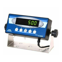
The Transcell TI-500E is a digital weight indicator designed for various weighing applications, featuring a 6-digit LED display and a straightforward keypad for operation. It serves as a central component in a weighing system, connecting to a scale platform via a load cell or junction box.

Function Description

The primary function of the TI-500E is to accurately measure and display weight. It supports both Gross and Net weight modes, allowing users to differentiate between the total weight and the weight of the contents after taring. The indicator can display weight in pounds (lb) or kilograms (kg), making it versatile for different regional standards. A key feature is its ability to establish a tare weight, which is useful for subtracting the weight of containers or packaging.

Beyond basic weighing, the TI-500E also offers a piece counting mode. This allows users to count the number of identical items placed on the scale platform, making it suitable for inventory management or packaging operations where item quantity is crucial. The indicator determines the average piece weight (APW) through a sampling process, and then uses this to calculate the total number of pieces.

The device is equipped with an RS-232 serial (COM) port, enabling communication with external devices such as computers or serial printers. This port supports various output strings and modes, including Demand Duplex Mode, Continuous Duplex Mode, and Auto Print Mode, facilitating data logging, remote display, and automated printing of weight tickets.

Usage Features

The TI-500E's operation is managed through a five-key keypad: UNITS, ZERO, NET/GROSS, TARE, and PRINT.

  • UNITS allows selection of the displayed unit of measure (lb or kg) and can also be used to change sample sizes in piece counting mode.
  • ZERO zeroes the weight display reading, provided the scale is stable and in Gross mode within a defined zero reset range. It is also used to navigate down into selection levels within the configuration menus.
  • NET/GROSS switches between Gross and Net weight modes and is used to save settings in the configuration menus.
  • TARE establishes a tare weight, subtracting the weight of a container from the total reading. It also serves as a "left" navigation key in the configuration menus.
  • PRINT sends the displayed weight reading to the serial communication port and acts as a "right" navigation key in the configuration menus.

The indicator features two main configuration menus: the Setup ("F") Menu and the User ("A") Menu.

  • The Setup ("F") Menu is accessed by a slide switch on the rear cover and controls metrologically-related parameters, including graduations, zero track band, zero range, motion band, digital filter, overload limit, calibration unit, display divisions, decimal point, and calibration procedures (zero, span, key-in zero, key-in span). It also includes a factory reset option and enables/disables the piece count feature.
  • The User ("A") Menu is also accessed via the rear slide switch and manages communication parameters (baud rate, data bits, parity, stop bits, serial transmission mode) and other miscellaneous settings like display check, disabling the UNITS key, serial port output string, ID number enable/entry, number of line feeds, handshaking enable, and print header settings.

Calibration is a critical usage feature, supporting both live calibration with actual loads and mV/V calibration using a load cell simulator. The process involves two steps: zero calibration (F16) and span calibration (F17). The indicator guides the user through placing loads and entering weight values for accurate calibration.

For piece counting, users first tare any container, then press UNITS to select a sample size (5, 10, 20, 50, or 100 pieces). After placing the sample on the platform and allowing stabilization, pressing NET/GROSS takes the sample, and the indicator displays the piece count.

The serial port can operate in different modes:

  • Demand Duplex Mode: Data is transmitted only when requested by pressing the PRINT key or receiving a host command.
  • Continuous Duplex Mode: Data is transmitted continuously at the end of each display update, suitable for remote displays.
  • Auto Print Mode: A one-time serial transmission occurs when a non-zero, stable condition is achieved.

Host commands can be sent to the indicator via the serial port to perform actions like printing, zeroing, taring, switching to Gross/Net mode, or changing units.

Maintenance Features

The TI-500E includes several features and guidelines related to maintenance and troubleshooting.

  • Error Messages: The indicator displays specific error codes (Err0, Err1, Err2, Err3, Err4, Err5, Err9) to alert users to problems such as overload, incorrect calibration values, insufficient signal from the load cell, non-volatile memory errors, or lost span calibration data. Each error message is accompanied by a possible solution, guiding the user on corrective actions like removing excess load, re-calibrating, checking connections, or contacting service.
  • Troubleshooting Guide: The manual provides a troubleshooting section addressing common issues like the unit not powering on (checking AC power, adapter, internal fuse) and erratic/unstable readings (checking for obstructions, loose connections, damaged load cell, or electromagnetic interference).
  • Factory Reset (F21): This function in the Setup Menu allows users to reset all "F" and "A" menu parameters to their default settings. This can be useful for resolving configuration issues, though it's cautioned that it will not overwrite previously saved calibration data.
  • Display Check (A4): Available in the User Menu, this function illuminates all digit segments, decimal points, and LCD annunciators in a test sequence, which can help in diagnosing display malfunctions.
  • Calibration View Data (F18): Users can view calibration values, which can be helpful for diagnostic purposes or verifying calibration integrity.

The device is designed for durability with an ABS enclosure (IP54 rating), offering protection against dust and splashing water, which contributes to its longevity and reduces the need for frequent maintenance in typical industrial environments. The internal fuse (1A 250V SLOW BLOW) provides protection against electrical overloads.

Transcell Technology offers technical support and a limited 12-month warranty against manufacturing defects, providing a clear pathway for users to obtain assistance or service if issues arise that cannot be resolved through the provided troubleshooting steps.

Transcell Technology TI-500E Specifications

General IconGeneral
ModelTI-500E
ManufacturerTranscell Technology
CategoryAccessories
TypeDigital Indicator
Display TypeLED
Display Digits6 digits
Communication InterfaceRS-232
Power SupplyAC 110/220V
Operating Temperature-10°C to 40°C
Humidity Range≤ 85% RH

Related product manuals