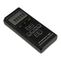
Reset for all Peak and Valley related items is achieved by holding the TARE ^ RESET key
depressed while momentarily pressing > PEAK.
7. Alarms
The SSI includes two solid state alarm relays rated 110 mA @ 350V peak, 35 ohms series
resistance. There is a common contact for the two relays. The active state of alarms is
shown by LED indicators: amber for Alarm 1, red for Alarm 2, and green for “Go” with no
alarm active. The “Go” LED can be disabled under the ALErt menu to conserve power.
With the Normal conversion rate, the relays can respond to the Unfiltered or Filtered value,
as selected under the FiLtr menu, to avoid triggering on electrical noise. The number of
consecutive readings in the alarm zone required to actuate the alarm is selectable in binary
steps from 1 to 128 (ALSet menu item) to avoid actuating on transients.
The action of the two relays is individually programmable with the ALSet menu item. Each
relay can be set to ON or OFF when the corresponding alarm is active, to be latching or
non-latching, to activate above or below the setpoint, and to operate with hysteresis or band
deviation.
Hysteresis, set under the dEU1H and dEU2H menus, controls alarm action symmetric-
ally around a setpoint. A high active alarm activates when the reading goes above the
setpoint by the hysteresis value and de-activates when the reading falls below the
setpoint by the hysteresis value. A narrow hysteresis band can be used to minimize relay
chatter around a setpoint due to electrical noise or signal feedback caused by load
switching. A wide hysteresis band can be used for control applications. The hysteresis
band is twice the hysteresis value.
Band deviation, set under the dEU1b and dEU2b menus, controls alarm action sym-
metrically around a setpoint to create a passband. A high active alarm activates when the
reading falls outside the deviation band, and de-activates when the reading falls inside. A
deviation value is set up around both sides of the setpoint to create a pass band. Band
deviation is often used in QA applications to pass or reject parts. The deviation band
equals twice the deviation value.
8. Keypad Lockouts
Many of the menu items can be locked out, or skipped, by changing appropriate lockout
digits from 0 to 1 under menu items Loc_1 through Loc_4. Skipping menu items that are
only used for initial meter setup has the advantage of simplifying meter operation and
reducing the chance of inadvertent setup changes. If an expected menu item does not
appear, always look for 1’s among the lockout digits before calling the factory for help.
9. External Control Inputs
By shorting one or both control inputs A and B to ground, the following items can be
externally commanded: Log, Tare, Tare Reset, Peak, Valley, Peak then Valley, Function
Reset, Meter Reset. Please see Section 6, “Connector Wiring Information.” These functions
are also available from the keypad unless locked out.

 Loading...