Installing an MP—Models MP-341 and MP-352
Chapter 3
Trapeze Mobility Point Installation Guide
Version 3.0
48
Confidential—Beta1 Draft—Confidential—Beta1 Draft—20 Sep 04
7 Insert the Cat 5 cable(s) into the connector(s):
● For a single connection, use the connector for port 1.
● For a dual-homed connection, insert one cable into each connector.
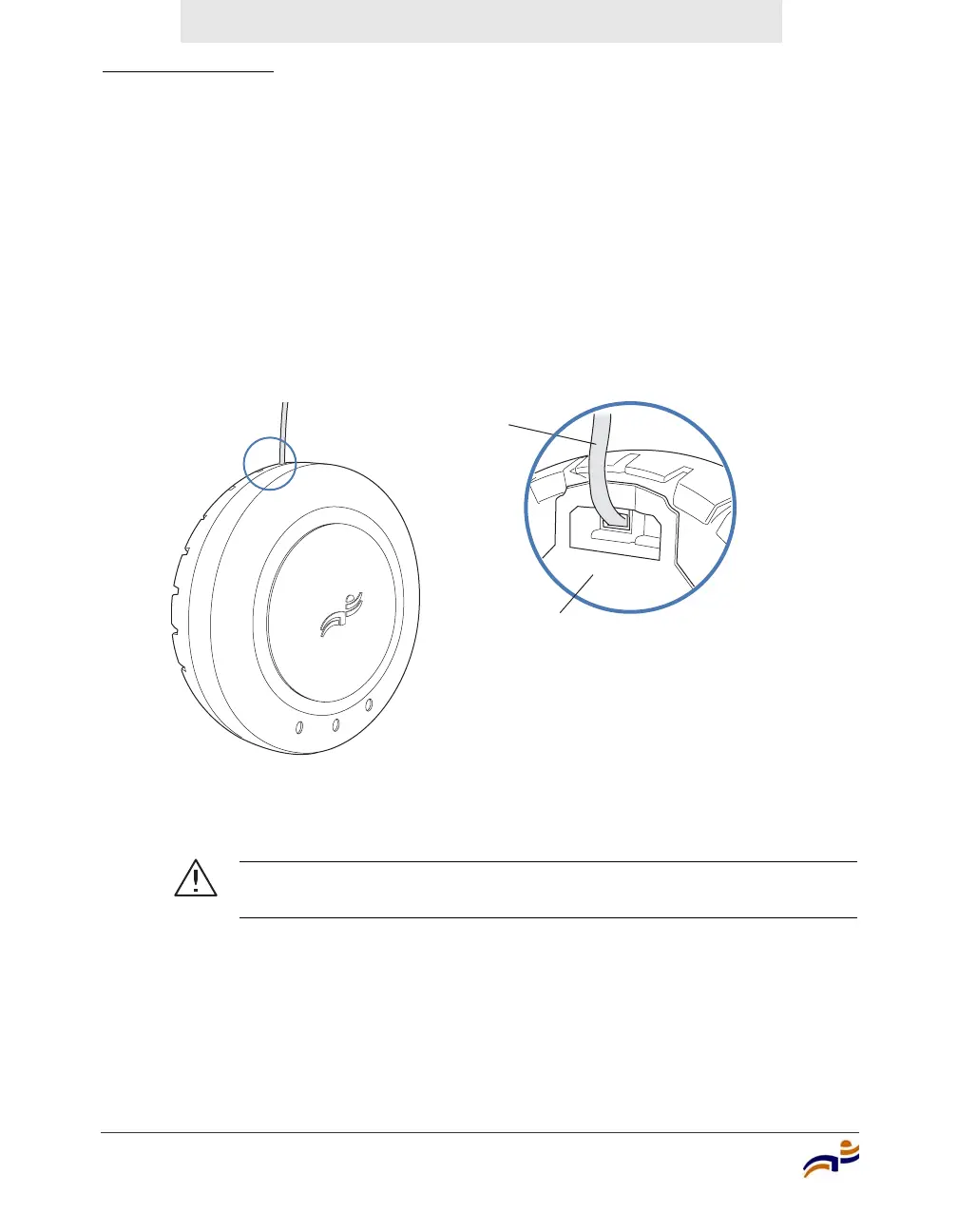
8 As shown in Figure 32, place the MP access point on the bracket, making sure
to remove any slack that occurs in the cable between the bracket and the MP
access point.
Figure 32. Step 8—Cable Placement
9 Lock the MP access point onto the bracket by inserting the 3-mm or 1/8-inch
screwdriver into the Lock hole on the access point as shown in Figure 33.
Caution! To prevent possible damage to the MP access point, make
sure the device is fully locked onto the bracket before letting go of it.
840-9502-0016
Universal mounting bracket
Cable


 To Next Page