Installing an MP—Models MP-341 and MP-352
Chapter 3
Installing and Connecting an MP
47
Confidential—Beta1 Draft—Confidential—Beta1 Draft—20 Sep 04
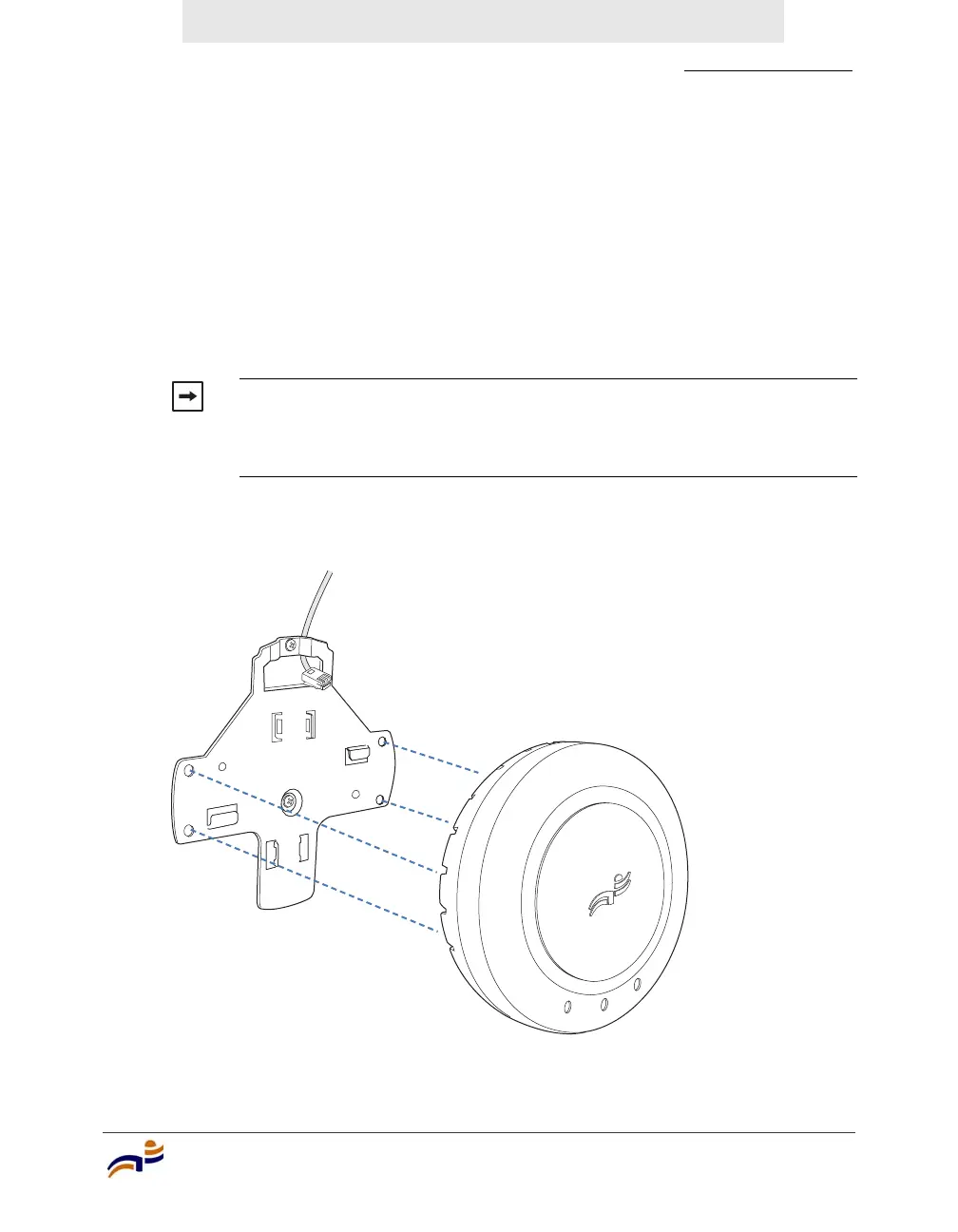
5 As shown in Figure 31, feed the Cat 5 cable(s) through the port connector
opening and align the universal mounting bracket over the drywall anchors so
that the two screw holes in the bracket face the drywall anchors.
6 Insert the #6 sheet metal screws into the screw holes, and tighten them to
secure the universal mounting bracket to the wall or ceiling.
(If you routed the Cat 5 cable through a hole in the wall or ceiling, insert the
screw into the center screw hole only.)
Figure 31. Steps 5 and 6—Bracket Placement on Solid Wall or Ceiling
Note. Do not insert screws in the four holes on the edges of the
bracket. (These are the holes indicated by the dashed lines in
Figure 31.) The MP access point fits into these holes. They are not
screw holes.
840-9502-0015


 To Next Page