IQ4E/.. Installation Instructions - Mounting TG201338 Issue 4, 19-Jan-2016. Applies to v3.33. 5
Installation Instructions - Mounting IQ4E/..
9
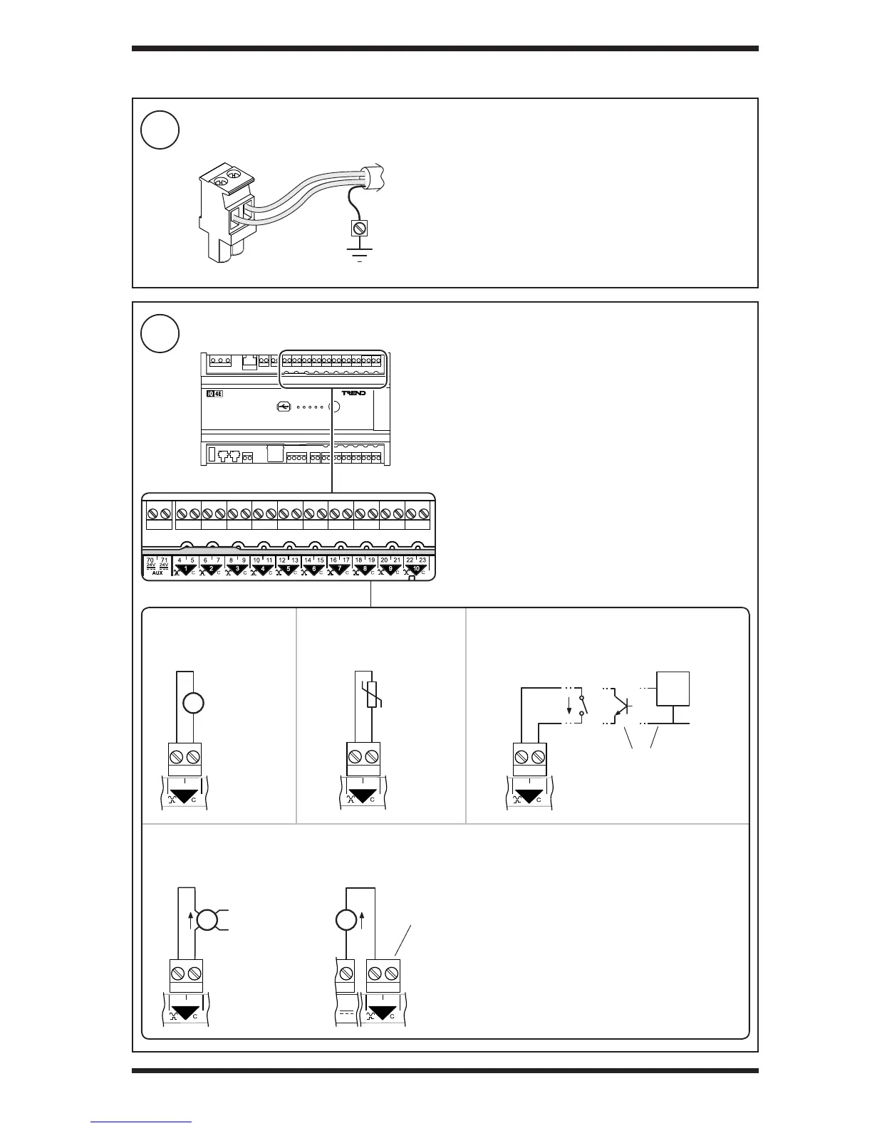
Connect Universal Inputs IN1 to IN10 (if required)
8
Connect Inputs/Outputs - Overview
3 INSTALLATION (continued)
Note: The input type (i.e. voltage, thermistor, digital or current)
is dened in the controller’s strategy.
ensure correct
polarity
Thermistor input
Current input
Voltage input Digital input
Terminal size: 0.5 to 2.5 mm
2
(20 to 14 AWG).
Terminal screw torque: 0.45 to 0.62 Nm (4 to 5.5 lb.in).
TP/1/1/22/HF/200 (Belden 8761) cable recommended for all
inputs/outputs.
Screened cable is not generally required unless the cable
passes through electrically noisy environments. Where it
is used the screen must be connected to the local panel/
enclosure ground and left unterminated at the far end.
Plug-in connectors with screw terminals
Externally powered Loop powered (using AUX output supply - see step 11)
External
Power
Supply
ensure correct
polarity
ensure correct
polarity
Common (C) terminal is linked internally to AUX
supply common - no connection required
volt free
contact
open
collector