LOCK/JIG
-13-
Centring the Jig
When using the Lock Jig, the clamp bar is used as
the datum edge. Before the jig can be used the
clamp bar datum has to be set by the user.
The jig central aperture has v notches that are
punched into the jig body. Due to manufacturing
tolerances the v notches should only act as an
initial guide to position the jig on the door.
Furthermore when the spacer fingers are used this
raises the jig higher making it more difficult to
align to the pencil marks.
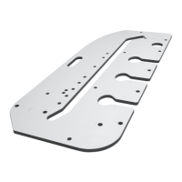
The laser cut line-up template has two v-point
wings that are bent down so that they are closer to
the door edge when fitted into the jig and ensure
the jig can be set up more accurately. The v-point
wings denote the centre of the line up plate.
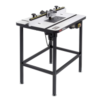
The v-point wings have been bent down to take
into account the jig plate thickness when no finger
spacers are used. If the jig us being used with
finger spacers the v-point wings can be bent down
further at the fold line with a pair of pliers to the
required height.
The central aperture notches are to be
used as an initial visual guide only,
always check the jig and template is
centred to the door before routing.
Th
n
a
g
te
a
ro
M
us
an
Please note v-point wings are sharp.
Please handle with care.
Tr
m
ha
pl
Trial cuts should be made on waste
material to check correct templates
have been selected and that jig is set
up accurately.
Do not over-tighten lobe knobs as
damage to the door or jig may occur.
To set up jig with the line-up template
■ After the lock position has been marked on
the door with a pencil, loosen the two lobe
clamping knobs and the three adjustable
levers (ratchet type which will require lifting
to change their position) so that the jig can fit
to the door.
■ Place line-up template into template aperture
recess of jig, ensure the v-point wings point
downward.
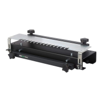
■ To set the jig accurately, adjust the two
clamping knobs to move the jig forward or
backwards to centre the v-point wings to the
pencil line on the door. Once the jig is
centred and parallel, slide the clamping knob
against the door edge and tighten the
adjustable levers.
■ Check clamping bar is fully against the door
edge and adjust adjustable levers if
necessary. The datum has now been set.
■ Remove line-up template and store carefully.
■ The jig can now be clamped into position by
tightening the two lobe knobs. Only gentle
pressure is required.
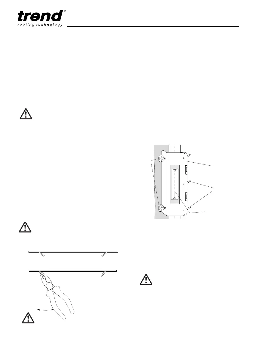
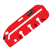
V-point wing height set
for no spacer finger.
Pliers can be used
to bend back the
v-point wing when
spacer fingers are
used.
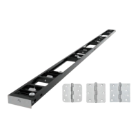
Adjustable
levers
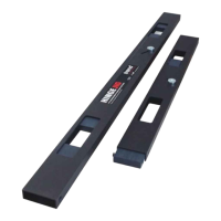
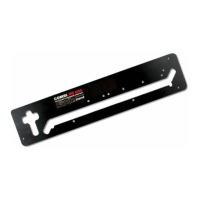
Clamp bar
(datum)
Lobe
knobs
V-point wing lined up
with pencil centre line
Line-up template in jig
template aperture recess.
Adjustable levers may require the
machine screw to be tightened with a
No.2 Phillips screwdriver before use.
■ Fit correct mortise or faceplate template into
jig for the actual mortise/face-plate required.
MANU-LOCK v9.1_MANU-LOCK v9 20/06/2013 09:05 Page 13