12" [30.5 cm] Min. Above
Grade / Highest
Anticipated Snow Level
Vent
Termination
12" Min.
[30.5 cm]
36" Max.
[91.4 cm]
12" Min. -24” Max.
[30.5 cm - 61 cm]
To Wall Typ.
28
CHAPTER 3
6. Locate the vent termination in a manner to protect
from damage by foreign objects, such as stones,
balls, or buildup of leaves or sediment.
7. Do not connect any other appliance to the vent
pipe or multiple boilers to a common vent pipe.
3.2.2 Category IV - Vent Installation - Sidewall
1. Vent pipe penetration through combustible or
non-combustible wall material must maintain a
minimum 1/4” [6 mm] clearance for 3” PVC/CPVC
vent or 1” [2.5 cm] for 2” PVC/CPVC vent. The diam-
eter of the penetration hole must be 4” [10.2 cm]
minimum for 2” and 3” pipe. When using Polypropyl-
ene or Stainless Steel Vent, refer to the vent manu-
facturer’s Installation Instructions for clearances.
2. The installer must use a galvanized metal thimble
for the vent pipe penetration.
3. Locate the vent pipe penetration to provide clearanc-
es as described in Fig. 17 and Fig. 19 on page 27.
4. The installer must comply with all local codes for iso-
lating the vent pipe as it passes through oors and
walls.
5. The installer must seal all exterior openings around
penetration with an exterior silicon caulk.
3.2.3 Termination Fittings - Sidewall
1. The vent and combustion air terminations must
include a factory supplied “bird screen” installed as
shown in Fig. 9 & Fig. 10 on page 18.
2. The combustion air piping must terminate at the
boiler with a 90º elbow.
3. The vent piping can terminate:
• Using a coupling as shown in Fig. 18 on page 27.
• Using a 90º elbow as shown in Fig. 19 on page 27.
Do not extend the vent pipe outside the side-
wall beyond the dimensions shown in Fig. 17
and Fig. 19 on page 27. Extended exposure
of the vent pipe could cause condensate to
freeze and block the vent pipe, resulting in
substantial property damage, serious injury, or
death.
WARNING
CHAPTER 3 - CATEGORY IV (INDOOR AIR) INSTALLATION OF VENT/AIR PIPING
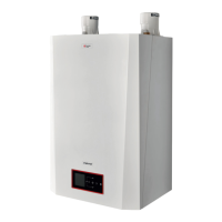
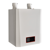
Fig. 20 - Category IV - Sidewall Termination of Multiple INSTINCT
Boilers
3.2.4 Category IV - Multiple Boiler Installation -
Sidewall
1. On installations of multiple INSTINCT boilers, termi-
nate each vent pipe as described in this manual.
2. Each vent termination must be a minimum 12” [30.5
cm] from the adjacent termination for installations
in the U.S. as shown in Fig. 20 below. For installa-
tions in Canada, provide clearances as required by
CAN/CSA B149.1.
• Fig. 19 shows one option for vent termina-
tions of multiple INSTINCT boilers. Either
termination option shown in Fig. 17 or Fig.
19 on page 27 can be used for multiple
INSTINCT boilers. The 12” [30.5 cm] mini-
mum distance between centerlines of the
vent piping must be maintained for any
chosen option.
• Reference Fig. 17 and Fig. 19 on page 27
for vent termination dimensions for each
unit installed in a multiple installation.
NOTICE
 Loading...