FMS-2000M
LIT-12013578
17
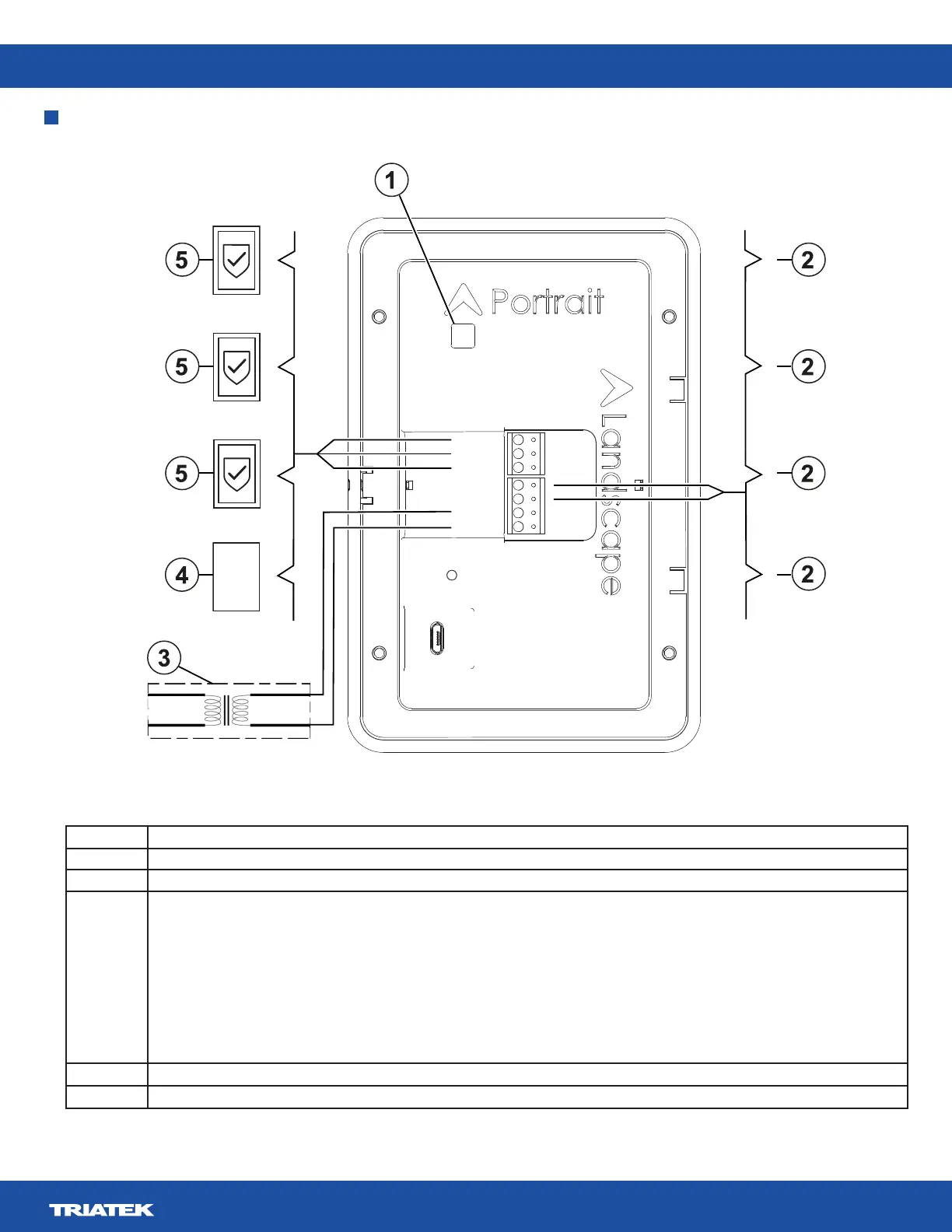
Wiring the system and BACnet MS/TP communications
+
24V_IN
–
+
DSPLY
RS485
–
+
BACnet
MS/TP
–
REF
120 VAC 24 VAC
Figure 11: FMS-2000M system wiring diagram
Table 7: FMS-2000M system wiring
Callout Component
1 DIP switch
2 Remote pressure sensor
3 Power supply
Note: The figure shows a 120 VAC to 24 VAC step down isolation transformer as an example. For information about correct power
supply termination, see the following wiring information:
• Wiring one remote pressure sensor to the monitor
• Wiring two remote pressure sensors to the monitor
• Wiring three remote pressure sensors to the monitor
• Wiring four remote pressure sensors to the monitor
4 Supervisory device
5 FMS-2000M Critical Environment Monitor