FMS-2000M
LIT-12013578
18
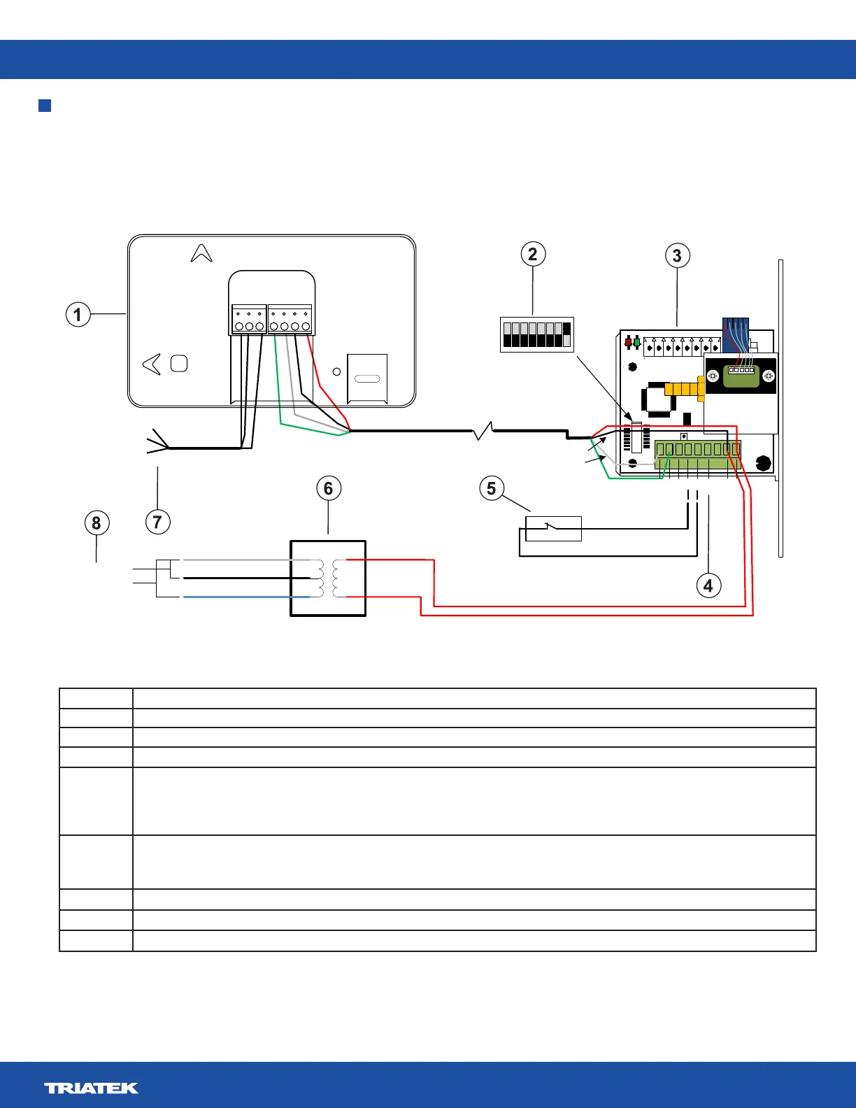
Wiring one remote pressure sensor to the monitor
Note: For optimum network communications, connect the reference signal (REF) to the COM terminal on the supervisory device’s FC
bus terminal block.
17
1
U2
33
49
7
5
1
CN1
S2
SW1
+Vin
-Vin
Io
+Vs
IN
GND
-
+
RS485
2
1
4
3
ADDR
6
JP4
LED1
LED2
RUN
PWR
JP5
CN3
5
JP2
24 VAC
Output
To BAS
network
-
+
Ref.
22 AWG stranded 3-wire
twisted pair, shielded
Supplied 10 � cable
Green
White
Black
Red
Green
White
Black
Red
}
Power input
P1
P2
COMMON
120 VAC input
240 VAC input
White
Black
Blue
+
-
+
-
+
-
REF
24V_IN
DSPLY
RS485
BACnet
MS/TP
Landscape
Portrait
120 VAC/240 VAC
60/50Hz input
Figure 12: Wiring one remote pressure sensor to the monitor
Callout Component
1 FMS-2000M monitor
2
3 Supplied remote pressure sensor
4 Io terminal
Note: A 4mA to 20mA signal is present at the sensor’s Io terminal which represents the monitored room pressure. You can use it to
remotely monitor room pressure when you connect the terminal to a third party controller on the BMS network.
5 Optional door switch
Note: Configure the door switch setting on the monitor. It can be normally closed or normally open.
6 Supplied power supply
7
8 AC power input options
Table 8: