TY96/97 VHF Radio Installation Manual 29 July 2016
01238-00 Issue AD
______________________
Page 12 Trig Avionics Limited
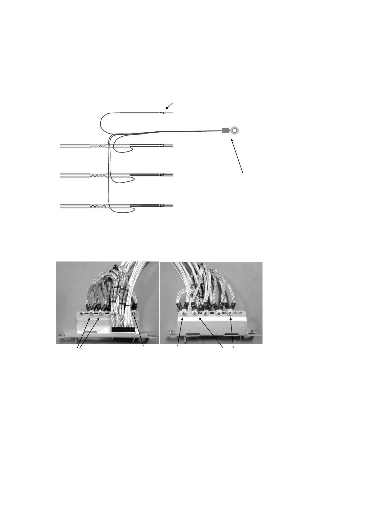
The signal ground wires from all the shielded cables should be grouped together and terminated with
another ring crimp along with a ground fly lead that will be used to connect to a ground pin on the 25
way connector.
The ground fly lead wire size should be 20 AWG and terminated with another D connector socket
contact.
5.4.7 Example Wire Harness
Below is a typical example of the TY96 wire connections, shown without the D-Sub backshell.
5.5 Antenna Installation
The VHF antenna should be installed according to the manufacturer’s instructions.
The following considerations should be taken into account when siting the Antenna.
The antenna should be well removed from any projections, the engine(s) and propeller(s). It
should also be well removed from landing gear doors, access doors or others openings which
will break the ground plane for the antenna.
Avoid mounting the antenna within 2 feet of a GPS antenna, and as far as practical from any
ELT antenna.
If the simultaneous use of two radio units is required then each antenna should be as far apart
as practicable for maximum isolation. We would recommend placing one antenna on top and
one on the bottom of the airframe. The Transmit Interlock function should also be used in this
Group signal
grounds together
and connect to
mounting tray
back plate.
Fly lead to ground pin
on the 25 way connector
Wire harness viewed from top
Wire harness viewed from bottom
Signal
ground
connections
Signal
ground
connections
 Loading...