4
DIP Switches 1-3:
The settings of DIP switches 1-3 define CAN address of the IO receiver
module. A unique address must be assigned when multiple modules
are used on a CAN network. If only one module is used on network
then all DIP switches should be set to ON position.
DIP Switch 1: On
DIP Switch 2: On
DIP Switch 3: On
DIP Switches 4-6:
The setting of DIP switches 4-6 define configuration of the IO receiver
module. Each configuration provides different functionality for keypad
and interior switches. Most customers use default configuration D
setting. See configuration setting definitions.
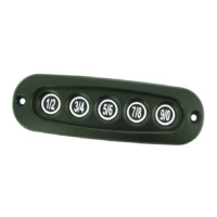
Keypad DIP Switch Setting Configurations:
Entering a 5-digit access code enables the keypad. After entering the
access code, one must press and release a 6th digit to unlock specific
doors or perform an operation according to the following list.
Configuration A [SW 4 off / SW 5 off / SW 6 off]:
Button (1 / 2) (1): Unassigned
Button (3 / 4) (2): Unlocks all entry and compartment doors
Button (5 / 6) (3): Unassigned
Button (7 / 8) (4): Unassigned
Button (9 / 0) (DB): Toggles Aux 1 output
Configuration B [SW 4 off / SW 5 off / SW 6 on]:
Button (1 / 2) (1): Unlocks all entry door(s)
Button (3 / 4) (2): Unlocks all entry and compartment doors
Button (5 / 6) (3): Unassigned
Button (7 / 8) (4): Unassigned
Button (9 / 0) (DB): Toggles Aux 1 output
Configuration C [SW 4 off / SW 5 on / SW 6 off]:
Button (1 / 2) (1): Unlocks all entry door(s)
Button (3 / 4) (2): Unlocks all doors assigned to relay bank A
Button (5 / 6) (3): Unlocks all doors assigned to relay bank B
Button (7 / 8) (4): Unlocks all doors assigned to relay bank C
Button (9 / 0): Unlocks all doors assigned to relay bank D