Page 12 of 16
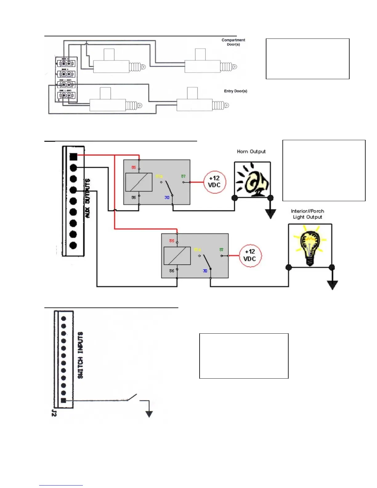
DIAGRAM 1: WIRING UP ACTUATORS TO I/O MODULE
DIAGRAM 2: AUXILIARY OUTPUTS WIRING
DIAGRAM 3: SWITCH INPUTS WIRING
Auxiliary outputs provide
relay driver ground signal.
Diagram to the left
illustrates typical relay
connectivity. As shown,
+12 V pin should be used
to
ower coil of rela
s.
Switch inputs are activated
when sunk to ground.
Diagram to the left illustrates
typical switch connectivity.
The cumulative current
draw of actuators at each
relay bank should not
exceed 25-amp rating.