Page 11 of 16
TABLE
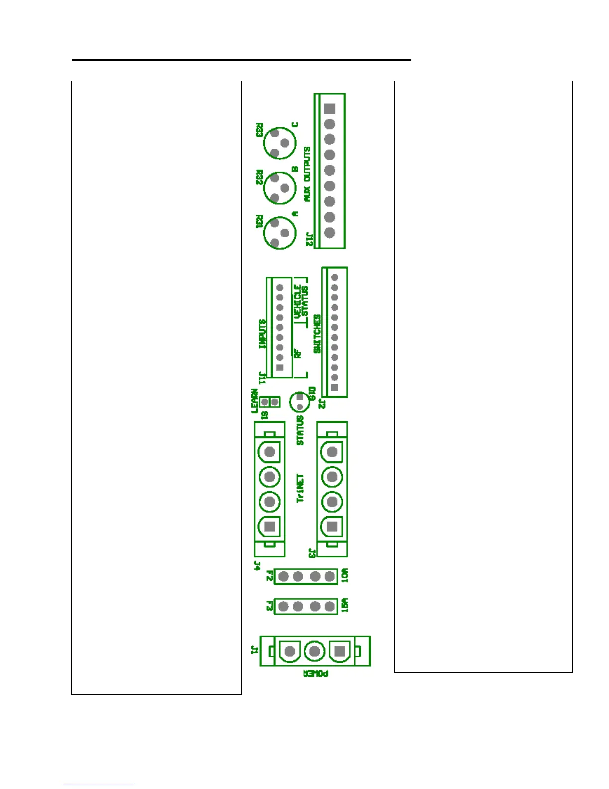
3: OTHER VEHICLE CONNECTIONS ON I/O BOARD
TRIMPOT A— Sets Timed
Dome/Porch Light Output (CW
Increases Duration)
TRIMPOT B—Sets Timed Aux 1
output (CW Increases Duration)
TRIMPOT C—Sets Timed Aux 2
Compartment Light Output (CW
Increases Duration)
J11 INPUTS: Inputs For RF Receiver
And Vehicle Status— Pin
Assignments:
PIN 9: Power/Ground (connect to +12 or
ground, depends if pins 7 and 8 are sinks or
sources)
PIN 8: Engine Running
PIN 7: Key Inserted
PIN 6: Panic Mode From RF Receiver
PIN 5: * Button from RF Receiver
PIN 4: Unlock from RF Receiver
PIN 3: Lock from RF Receiver
PIN 2: +12 VDC to RF Receiver
PIN 1: Ground to RF Receiver
S1 LEARN INPUT: Input To Reset
Keypad Codes
D19 STATUS LED
J3 AND J4 TriNet: Keypad
Connectors
PIN 4: TriNet B
PIN 3: TriNet A
PIN 2: Ground
PIN 1: +12 Volts
J1 CONNECTOR: Connect to a
Reliable Power Source.
PIN 3: GND
PIN 2: GND
PIN 1: +12 V
J12 AUX OUTPUT: Relay Driver Outputs - Pin
Assignments
PIN 1: +12 v
PIN 2: Horn
PIN 3: Headlight Or Marker Lights
PIN 4: Interior Light / Porch light
PIN 5: Auxiliary 1
PIN 6: Auxiliary 2-Compartment Lights
PIN 7: Entry Door Ajar
PIN 8: Compartment Door Ajar
PIN 9: Siren
OTE: Pins 2-9 Sink To Ground Upon Activation. Pin 1
To Be Used As (+12 V) Opposite Side Of Relay Coil.
J2 SWITCH: (connect to ground to activate)
Pin Assignments:
PIN 12: Security System
PIN 11: Compartment Door Ajar
PIN 10: Entry Door Ajar
PIN 9: Auxiliary 2 Toggle
PIN 8: Auxiliary 1 Toggle
PIN 7: Actuate Zone 6
PIN 6: Depends On Dip Switch Config.
PIN 5: Depends On Dip Switch Config.
PIN 4: Depends On Dip Switch Config.
PIN 3: Depends On Dip Switch Config.
PIN 2: Depends On Dip Switch Config.
PIN 1: Depends On Dip Switch Config.
OTE: PINS 1-6 Provide Different Locking And
Unlocking Functions. Their Relay Bank
Assignment Depends On S2 DIP Switch Setting.
The Connection Of Both Pin 8 (Aux 1 Toggle)
And Pin 7 (Actuate Zone 6) Is Not Recommended.
F2: RED 10-amp fuse protects Trinet
Communications (Power And Communication) to
the keypad.
F3: BLUE 15-amp fuse protects the power
actuator outputs of the I/O module.