Page 6 of 16
Trim Pot Variable Resistors (diagram on page 11):
These trim pots provide adjustable settings for timed outputs. Clock-wise rotation increases
activation time. Trim pot A (R31) is assigned to dome/porch light activation (5-60 second
range). Trim pot B (R32) is assigned to Auxiliary 1 output (0.5-5.0 minute range) and trim pot
C (R33) is assigned to Auxiliary 2 compartment lighting output (0.5-5.0 minute range). Trim
pot settings are updated every 30 seconds. Trim pot adjustments may not be observed
immediately.
S2 DIP Switches:
The S2 DIP switch is located under the I/O module cover. Functional assignments are
described below.
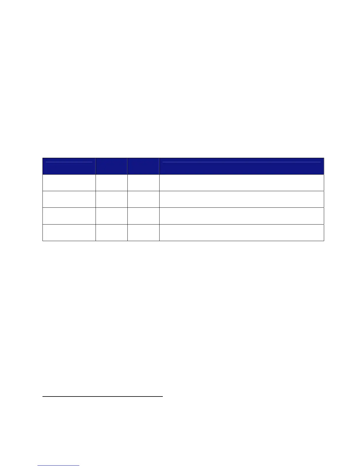
• Switches 1 and 2 provide a functional assignment of how relay banks A-D are
grouped. The following table shows the DIP switch assignment, configuration type
(A-D), and subsequent relay assignment. Configuration D is standard.
Configuration
Switch
1
Switch
2
Relay bank grouping
A Off Off
1 group exists. All banks are grouped with entry
door.
B Off On
2 groups exist. #1 entry group. #2 group to banks
A, B, C, and D.
C On Off
5 groups exist. # 1 entry. #2 to bank A. #3 to
bank B. #4 to bank C. #5 to bank D.
D On On
3 groups exist. #1 entry group. #2 group to banks
A and B. #3 group to banks C and D.
• Switch 3 provides the ability to deactivate auto locking and unlocking via engine
running input.
o Switch 3 ON: auto locking and unlocking activated.
o Switch 3 OFF: auto locking and unlocking deactivated.
• Switch 4 provides the ability to designate the functionality of the Cargo Lock and
Cargo Unlock buttons. Switch 4 ON is standard position.
o Switch 4 ON: buttons lock and unlock compartment doors
o Switch 4 OFF: the Cargo Lock button initiates the panic function. The Cargo
Unlock button toggles the Auxiliary 1 output on/off. (See page 7)
S1 Learn Switch Connector:
The Learn Switch Connector is used to reset the keypad to assign a new authority code.
See pages 11 and 14 for further information on teaching keypad a new authority code.
Status LED (diagram on page 11):
LED flashes at power-up and provides short periodic pulses if voltage supply is low.
Miscellaneous I/O Module Features:
Door locking and unlocking−A short single pulse output provides locking operation and 2
short pulse outputs provide unlocking operation. The locking and unlocking pulses have
opposite polarities. Locking and unlocking operations are activated via vehicle switch inputs
or according to e-PAD and e-FOB
instructions above.