6
2.0 INSTALLATION
2.1 Orientation
The flow meter can be mounted in any orientation. However, for optimum
performance and ease of inspection, it is desirable to mount the flow meter in a
horizontal section of pipe. This ensures the rotating piston is not influenced by
gravity when at rest.
2.2 Meter location
The flow meter should be fitted upstream of any flow control or cut-off valve. This
prevents free discharge from the flow meter and minimises the risk of drainage
and air entrapment which may cause erroneous readings on start up.
The Multipulse positive displacement flow meter does not require any flow
conditioning, therefore straight runs of pipe before and after the flow meter are
not necessary.
The flow meter is not to be exposed to any form of hydraulic shock or over
speeding as this could damage the internals.
2.3 By-pass Installation
It is our recommendation the flow meter be installed in a by-pass section of pipe
with isolation valves to enable the flow meter to be isolated during pipeline
purging. If a by-pass is impractical, flush the pipe work to purge out foreign
matter such as rust, welding slag and sealing compound prior to installing the
flow meter or temporarily remove the piston, partition and centre bearing to allow
free passage of the foreign matter.
The by-pass configuration should also be used if the system is exposed to
periodic steam or air purging. ( See 5.0 Cleaning In-Situ )
2.4 Strainers
It is sound practice to locate a suitably sized strainer immediately upstream of
the flow meter. Recommended strainer mesh sizes are;
Model No. Mesh size Microns
MP015 100 150
MP025 / MP040 50 250
MP050 25 500
A range of strainers are available to suit both the Multipulse PD and Turbopulse
turbine meter range.
7
2.5 Commissioning
Immediately after installation or after long periods of shut down, the flow meter
must be slowly purged of air. This can be achieved by allowing the liquid to flow
through the flow meter at a slowly increasing rate until the air is released.
When metering liquids with a viscosity greater than that of water, the maximum
flow rate must be reduced to a level that will produce a pressure drop across the
flow meter of no more than 280 kPa ( 2.8 bar ).
The flow meter is now ready to put into service and will accurately measure all
liquids passing through it, provided it is not operated outside its specified limits.
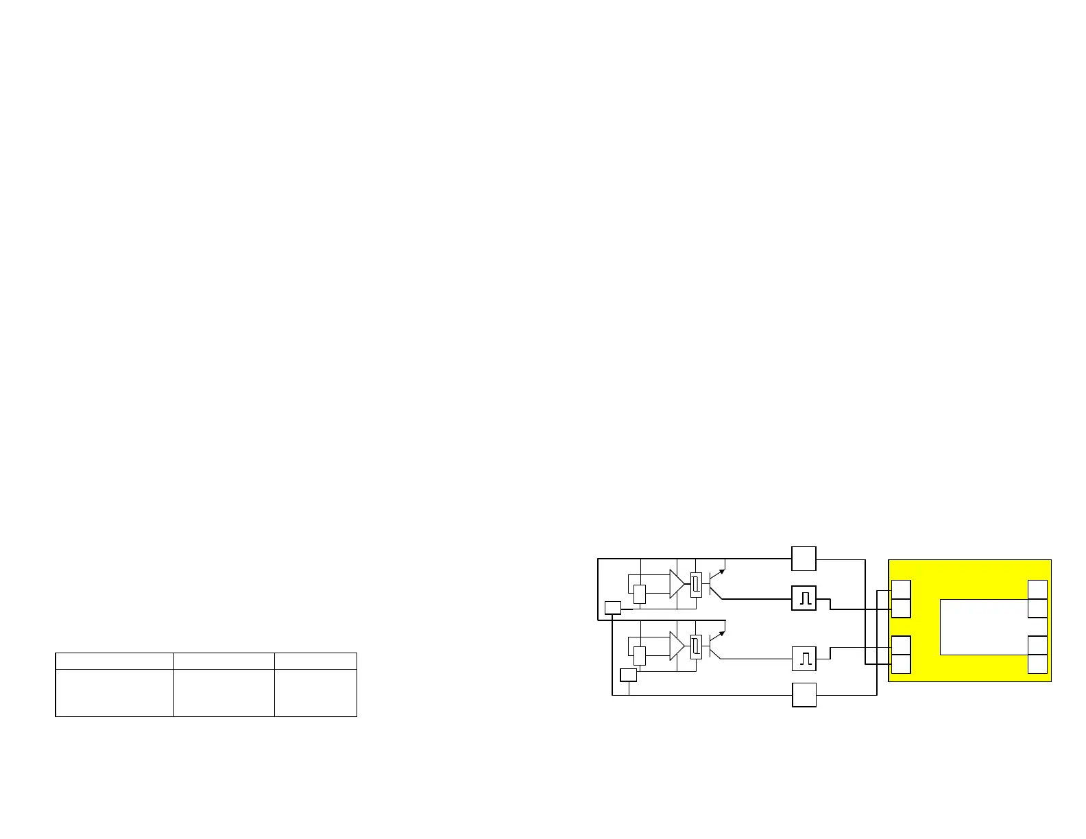
2.6 Reverse flow (bi-directional flow)
The flow meter is capable of accurately measuring flow in the reverse direction.
Meters fitted with the QP output option (quadrature pulse output) may be
interfaced with the Trimec Pulse Discriminator Module (PD1) to separate
forward & reverse flow output pulses for input to the appropriate totalising
registers or add and subtract counter input.
It is important to note that the Quadrature Pulse option has the same pulse
resolution (pulses/unit volume) as that of the reed switch for each size
Multipulse flowmeter.
Where reverse flow is not to be registered it is wise to install a check valve
upstream of the flow meter.
Flowmeter with QP outputs
PD1 Pulse Discriminator
-
+8~24Vdc
1
2
5
4
Output signals
Sig.1
Sig.2
-0V
+Vdc
10
9
5~24Vdc
Vdc
Output Signal 1
Ground
-0V
Reg
Output Signal 2
Reg
7
6