Page 20
Page 1
TABLE OF CONTENTS
1. INTRODUCTION
1.1 Model number designation 2
1.2 Specifications 3
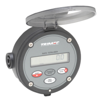
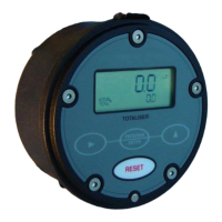
1.3 Overview 4
1.4 LCD displays 4
2. OPERATION
2.1 Accumulative total 5
2.2 Resettable total 5
2.3 Rate display 5
2.4 Keypad function matrix 5
3. INSTALLATION
3.1 Mounting - integral mount 6
- wall mount 6
- pipe mount 7
- panel mount 7
3.2 Flowmeter connections - unpowered sensors 8
- powered sensors 9
3.3 Wiring connections - external powering & remote reset 10
- loop powering 10
- scaled pulse output 10
- alarm outputs 11
- wiring requirements 11
4. PROGRAM PARAMETERS ( models RT11& RT12 )
4.1 PIN number protection 12
4.2 Resetting accumulative total 12
4.3 Engineering units 12
4.4 K-factor (scale factor) 12
4.5 Rate conversion factor 12
4.6 Rate dampening ( see response graph page 19 ) 12 & 19
4.7 Scaleable pulse output 12
4.8 Non linearity correction ( NLC) 12
4.9 Presetting power levels 13
5. PROGRAM PARAMETERS ( model RT12 only )
5.1 Analog output 13
5.2 Flow alarms 13
5.3 Flow alarm deadband 13
5.4 Dual flow inputs 13
6. PROGRAMMING FLOW CHART
6.1 Model RT11& RT12 program levels 1~7 14
Model RT11& RT12 program levels 8~12 15
6.2 Model RT12 program levels 13~23 16
6.3 Program detail record 17
7. TERMINAL DESIGNATION
18
8. ALPHABETICAL INDEX 21