Page 12
4. PROGRAM PARAMETERS
4.1 PIN No. Program Protection
The option exists to activate PIN number program entry. If activated the user must input a
four digit PIN number. Failure to input the correct PIN number will deny the ability to change
any of the program parameters but will allow the user to step through and view the previously
set program details.
Only one PIN number may be set but this can be changed at any time after gaining access
through PIN entry. A second back up PIN number is installed at the factory should the
programmed PIN be lost or forgotten. ( refer bottom of page 17 for the back up PIN No. )
4.2 Resetting Accumulated Total
Resetting the accumulated total can only be done at level 2 (L2) in the program mode.
4.3 Engineering Units ( refer clause 1.4 )
Select from available Engineering units to right of the display. No eng. units denote NIL set.
4.4 K-factor (scale factor)
Enter K-factor starting with the most significant number, up to 7 prime numbers & 3 decimal
numbers can be entered. Trailing decimal numbers move into view as digits to the right are
progressively selected, any significant digits which may move from view remain functional.
4.5 Rate conversion
Rate conversion is seldom used, it is explained at level 6 in the program chart on page 14.
4.6 Rate dampening
Dampening is available to smooth out fluctuating flow input signals in order to provide a
stable rate
readout & analog output. Most input signal are reasonably stable and need only a
low setting value of 40 to 70 ( see response graph on page 19 ).
4.7 Scaled Pulse Output ( Instrument must be externally powered as per page 10 )
The output pulse is NPN/PNP link selectable and capable of switching up to 1 amp max.
The scaling of the pulse output is set as the number of litres / gallons etc. per output pulse
Eg. 0.1 litres/pulse, 10 litres/pulse, 100 gallons/pulse. Range is 0.1 - 9999.9 Eng.unit/pulse.
The pulse width (pulse duration 1:1) automatically adjusts to the output frequency defaulting
to a maximum pulse width of 300 milliseconds at frequencies below 1.66hz. To calculate
pulse width at higher frequencies use: 1000 ÷ (hz x 2) = pulse width in milliseconds.
4.8 Non Linearity Correction ( NLC ) - Linearisation
Linearisation enables the instrument to correct for known non-linearities in a flowmeter
thereby improving the overall accuracy and in many cases the effective flow range
(turndown) of the flowmeter. Refer to program level L11, page 15 for setting NLC points.
NLC can be used without external dc power however, battery life is considerably reduced
according to usage.
Note: The RT defaults out of the program mode if no entries are made after 4 minutes.
Page 9
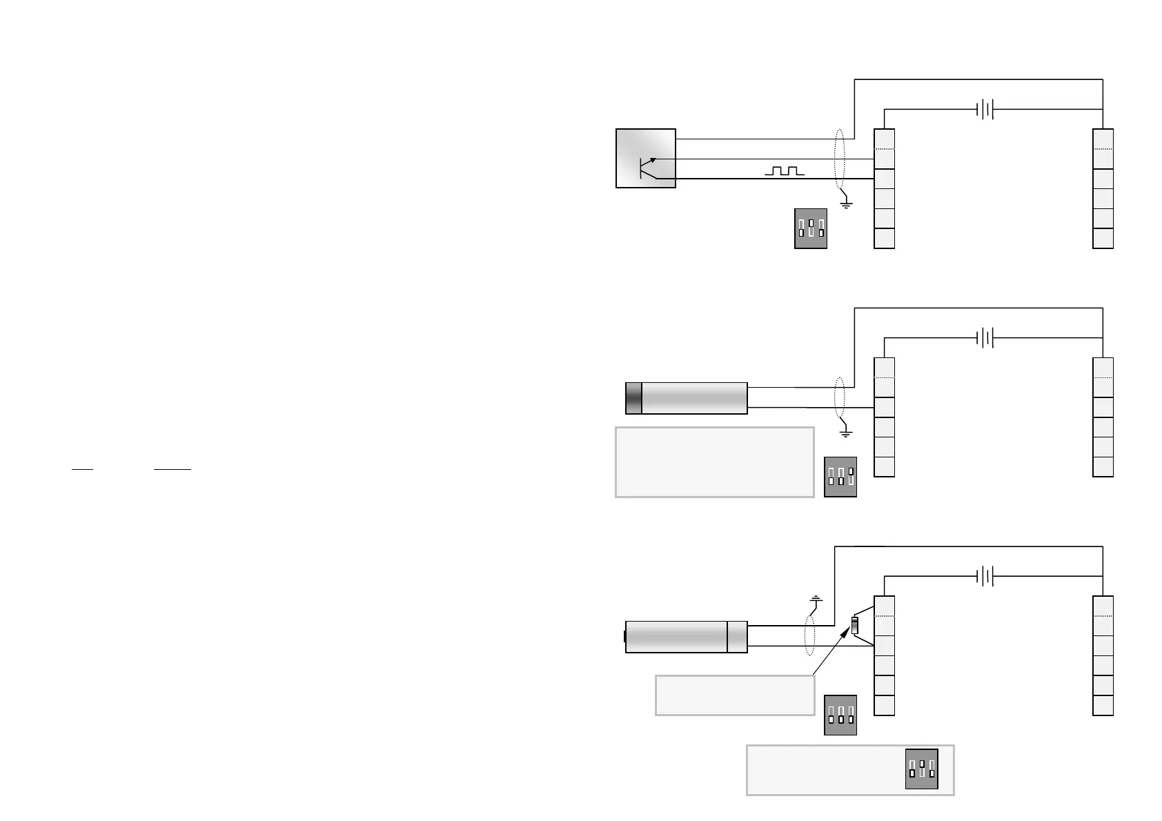
3.2 Flowmeter connections ( powered sensors )
NOTE : Voltage not to exceed 13.4 Vdc
through an approved barrier if when using
an intrinsically safe NAMUR proximity in a
hazardous area ( EEx Ia 11C ). Typically
these proximity’s are limited to 8.2 Vdc
5. Namur - Inductive proximity switch
NAMUR
Inductive Proximity
-
+
6
5
4
3
2
7
8
9
10
11
High flow alarm
Low flow alarm
Scaled pulse output
Remote reset
+ 8~24VDC supply
- 4~20mA output
+ 4~20mA output
Flow input B
Flow input A
-0V Ground
12 1
-0V Ground + 8~24VDC supply
8~24 Vdc reg. suppl
- +
ON
1 2 3
4. Hall Effect ( open collector )
Vdc supply
- 0V ground
+ Signal out
Hall effect
6
5
4
3
2
7
8
9
10
11
High flow alarm
Low flow alarm
Scaled pulse output
Remote reset
+ 8~24VDC supply
- 4~20mA output
+ 4~20mA output
Flow input B
Flow input A
-0V Ground
12 1
-0V Ground + 8~24VDC supply
8 ~ 24 Vdc reg. suppl
- +
ON
1 2 3
Default setting for input B if
input B is not being used.
ON
1 2 3
NOTE : Position a 100 ohm
x ¼W resistor across terminals
1 & 3 or 2 & 3 as shown
6. Current pulse
Current modulated pulses
4mA mark & 20mA space
6
5
4
3
2
7
8
9
10
11
High flow alarm
Low flow alarm
Scaled pulse output
Remote reset
+ 8~24VDC supply
- 4~20mA output
+ 4~20mA output
Flow input B
Flow input A
-0V Ground
12 1
-0V Ground + 8~24VDC supply
9~24 Vdc reg. suppl
- +
ON
1 2 3
Coil with pre-amp
current modulated
-
+
A
B